
Grounding, different grounds/planes, RTN, for multi-output 50W PSU based on InnoSwitch3-CE
Hello,
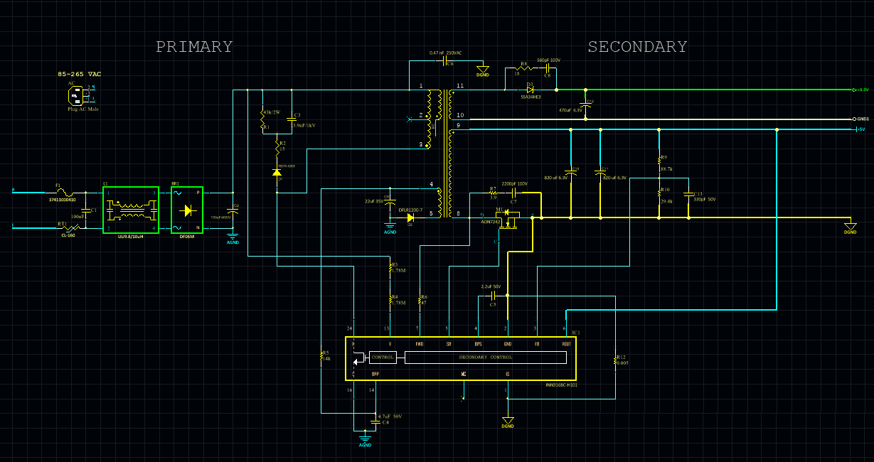
I'm trying to implement the PI-Expert generated PSU circuit (attached) based on the InnoSwitch3-CE.
The first thing I noticed is the missing circuit for current sense resistor. According to the datasheet of the device, it has to be connected across GND and IS pins of the device. Example application circuit in the datasheet, as well as other implementations, show a 0.005 ohm resistor tied between GND pin, and IS pin/RTN port. The datasheet says the following about GND pin:
"SECONDARY GROUND (GND) (Pin 2) GND for the secondary IC. Note this is not the power supply output GND due to the presence of the sense resistor between this and the ISENSE pin."
If this is not the power supply output GND, why it is tied to RTN > Signal GND (marked in pink in the attached circuit)?
One more thing, grounding, separate grounds/planes requirements look a bit vague to me in this design. How each of these GND signals must be dealt with in the PCB? Why the 3.3V winding has a different ground signal (GND1)? Is this tied to the other grounds, RTN, on the PCB?
I still have more questions about current/voltage regulation, but I would first leave those until I hear from someone about the above.
Thank you for your time and attention!
Files
| Attachment | Size |
|---|---|
| 50W, two output, PSU based on InnoSwitch3-CE | 196.74 KB |
Comments
Hi,
Thank you for the follow up. Makes sense now. However, I couldn't enable 'AC_Stack' on both outputs. It says I have to change the type of output. When I tried to change the type of output "main output arrangement" I got another error messages saying that the circuit design is out of limit and I have to contact engineering for more info.
I have attached the design file if you want to take a look. Also, the screenshot shows the final circuit drawn based on this design, with the sense resistor added. It would be great if you can take a look and advise whether the design looks good and free from any issues.
Thank you for your help!
| Attachment | Size |
|---|---|
| InnoSwitch3-CE_PSU_Z1.uds | 473.5 KB |
| Final_PSU.jpg | 364.3 KB |
By the way, it would be great if PI would consider adding features to allow user-level circuit input/modification, as well as, export to Allegro/Altium schematic in the upcoming versions.
** update **
I believe I have accidentally isolated the 3.3V output from the 5V one. The problem is, I have already ordered the transformer shown in the design and changing the output type to AC_Stacked would probably need a different transformer. A common GND has to be used for both of the 3.3V and 5V domains.
I have been waiting for any feedback on last question I sent for several weeks now. I asked the same question on several discussion forums, and the answer was that I can combine grounds for two secondaries. I still did not order the board, but I already received the transformers.
Could someone here please tell me what's wrong in combining grounds for two isolated secondaries? I've seen the same across several designs with a 10 ohm resistor placed across the two different grounds.
You cannot AC stack both outputs since the resulting AC stack will require the 3.3V output to be stacked below the 5V output. The InnoSwitch requires at least 4.4V on the VO pin to provide power to the secondary controller. With 3.3V as the lower stack, the VO and FW pin will have to be connected to this output and will not be able to provide power to the InnoSwitch. This is why AC stacking is not possible in your case - you will have to float both outputs.
PI Expert will soon support schematic export to Eagle, Altium, PADS, OrCAD, KiCAD, etc. Keep an eye out.
Hope this helps.
Thank you very much for the follow up. I have updated the circuit to use additional SR output for 'output2' and now I believe the ground is common for both secondaries. However, this change came at the expense of changing the specs for the transformer. Like I said earlier, the transformers are already ordered.
The new design file has been attached if you want to take a look. Do you think the transformer made according to first design still fits this updated circuit?
Thank you again.
| Attachment | Size |
|---|---|
| InnoSwitch3-CE_PSU_Z_review.uds | 369.5 KB |
| PSU_Dual.jpg | 120.17 KB |
I suggest you change the FS and VOR to match the transformer you have ordered to ensure performance. Start by setting the NS (secondary turns) and changing the VOR to achieve the NP (primary turns). Once done, change your FS (switching frequency) to achieve the target inductance. This way, the tool will also be able to warn you regarding potential issues with the design that uses your previous transformer.
Thank you very much. That was very clear!
Hi,
For current sensing, the sense resistor has to be placed in series with the path of output current flow. The voltage developed across this sense resistor is fed to the IS pin for current sensing. The current sense resistor is missing since you are creating an isolated multi-output design. Why? Beyond what I already mentioned, current sensing will only work on the output which is connected to the FWD and VO pin - in your case, it is the 5V, 8A output. The 3.3V, 1.5A output is isolated from the 5V, 8A output which is why is has an independent ground (GND1). It should not be connected to any other ground/return. Unless VO and FWD are connected to this output, current sensing/limiting will not be possible on it. The tool currently only supports IS pin protection if the two outputs are non-isolated (AC-stacked). You can AC-stack both outputs by navigating to Specifications->Stacking from the navigation tree on the left. By doing so, the IS-pin circuit will appear. Keep in mind that since both outputs have a common GND in an AC-stacked configuration, the IS pin protection current is the total current of both outputs. Hope this helps.
PI-Lupin