
Design of AC/DC 12V @ 1A power supply with TNY286DG-TL
Hi evertone,
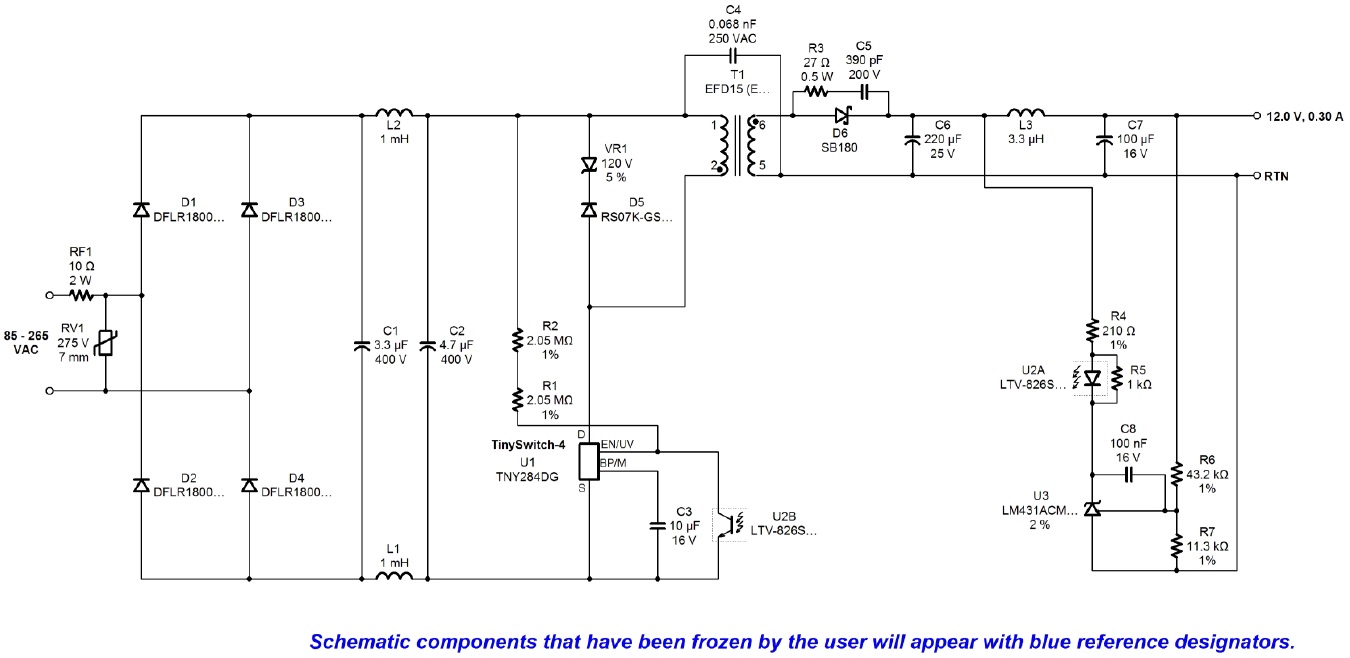
I'm using the TNY286DG-TL chip along with the PI EXPERT tool to design a 12V/1A power supply. I've created a diagram, but I have concerns about the transformer I'm using. My question is: Will the design I'm showing below work correctly at 220VAC @ 60Hz?
Files
| Attachment | Size |
|---|---|
| img1.jpg | 143.97 KB |
Comments
Hello,
I am using a dual-channel optocoupler as suggested by PI EXPERT, and I didn't want to deviate too much from the design recommended by the software. However, I am encountering an issue with the transformer because the software recommended a different core and number of turns for the windings. I am currently using a commercial transformer, and its specifications are provided in the same image
I doubt that PIExpert suggested a dual optocoupler when a single one would do. Please pass along the PIExpert design. The transformer specifications shown in the schematic do not provide sufficient information to evaluate the design. Number of turns and core type are also needed.
I just ran the design in PIExpert, (2 outputs, each with 12V/0.3A) and it specified a single channel optocoupler. It also suggested a transformer with an EE16 core and an inductance similar to that of the transformer you're using.
We also have a transformer prototyping service, which you can access here:
https://www.power.com/design-support/rapid-transformer-sample-service-rtss
Hello, There could be two things happening here; either I don't fully understand the design or there might be something unusual because I can clearly see a dual-channel optocoupler. I'm showing you the complete design in 'img2' and the component specifications in 'img3'. If I am making any mistake, please let me know. Regarding the transformer, I'm using an EF 16 core. Should I expect it to work correctly?
Here's the design I ran on PI expert. Download it and open using PIExpert. It clearly shows a single channel optocoupler.
| Attachment | Size |
|---|---|
| TinySwitch-4_12V_2out_7W2.uds | 466.5 KB |
Can you post a copy of your PI Expert design file showing the 2-channel optocoupler? We need this information in order to fully understand what is happening in your situation. Also, I cannot comment intelligently on the XFMR design without the turns data - the turns ratio is not sufficient.
It looks like there is an error in the PI Expert optocoupler database whereby the LTV826S is listed as a 4-pin single package rather than a dual device. I have alerted our software team to the problem so it can get fixed. You were unlucky in that that device was selected as the default device for the design. When I ran the same design, PI Expert selected the PS2501, a single-channel optocoupler.
You still need to add preload resistors to the two outputs to avoid issues with cross regulation. Without the preload, if you reduce the load on the regulated output to zero, the unregulated output voltage will collapse. Conversely, if you run the regulated output up to maximum load with no preload on the unregulated output, it will most likely go grossly out of regulation on the high side.
Hahaha, I knew I had seen a dual-channel optocoupler! I hope everything goes well solving that. Regarding the preload resistors, I placed a 1k one on both outputs. I hope that's sufficient. Thanks for all the help!
Probably not sufficient. 10% load is more in line with what you need, so more like 390 ohms or so. Don't expect any better than 10-15% regulation on the unregulated output.
Since you are running a common ground for both outputs, you can also try sharing the regulation between the two outputs.
This will make the regulation a little better on the unregulated output at the cost of somewhat worse regulation on the regulated output. You can do this by increasing the top divider resistor on the regulated output by 10% or so, and adding a resistor from the unregulated output to the TL431 reference pin calculated to get 12V on the unregulated output. It may take some juggling of values to balance the regulation between the 2 outputs. This also needs to be combined with the 10% preloads mentioned here as well.
Why are you using a dual channel optocoupler when a single channel device would be totally adequate? You will probably need preload resistors on both 12V outputs to get decent regulation over extremes of load. Start with ~10% preload for each output. Which voltage input range did you input into PI Expert? If you specified either universal input (90-264 VAC) or high range input (180-264 VAC) the transformer design generated should work.