
Poor regulation
Hi,
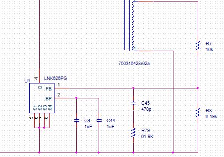
I have a offline application using the LNK626PG part. It has a 24V output at 50mA, 5V output at 1A, and 3.3V output at 0.5A. I built a initial prototype and it worked fine across the load range. I now built a much more compact version and the regulation is very poor. As I load the 3.3V and 5V the voltage drops on the outputs. Right now I am using self bias on the BP pin (just two 1uF caps across the BP pin and the S pin). The feedback winding is a single winding not center tapped. I have a 10k resistor coming off of the feedback winding to the FB pin and then a 6.19k Ohm resistor from the FB pin to the S pin. I have a 470pF cap and 61.9k resistor in series across the FB pin to the S pin. See attached schematic.
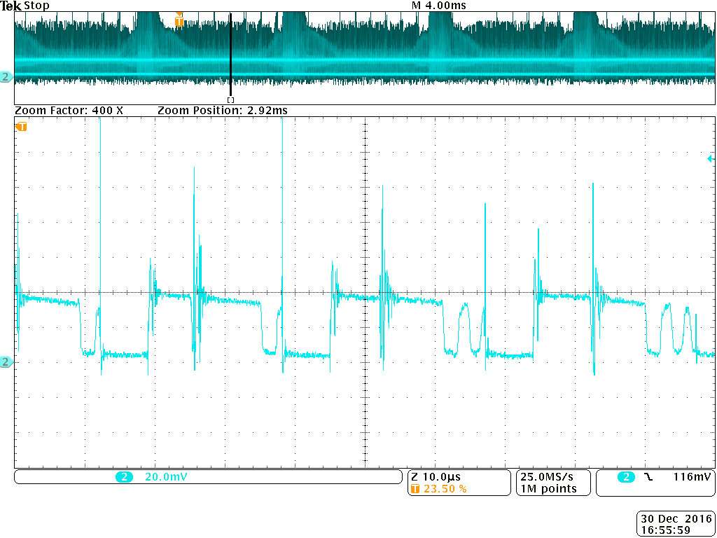
I attached a screen capture of the feedback pin when the 3.3V and 5V outputs are loaded. TEK00383
I noticed that some of your schematics show a external bias circuit fed from the feedback winding. When should this be used instead of just self biasing the BP pin and only using a 1uF cap across it as I am doing? Will adding this external bias circuit improve my regulation?
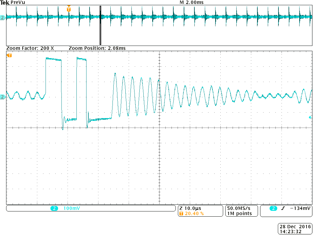
I noticed that during full load there is a instance where the switch only turns on for a very brief period of time before turning back off. Is this due to noise? See TEK00370 file attached. This is the primary transformer voltage during full load with 90VAC input. I did not see this in the old design that worked.
I attached anoher image of the same primary voltage but with no load. See file TEK00366.
Let me know if you have any ideas on what is wrong.
Thanks
Files
Comments
In order to make sure it was not the transformer, I took the transformer from the first prototype that worked and put it in this version of the board. It performerd the same as the new transformer. The design still had regulation issues. Yesterday I actually had some improvement by adding a 0.1W load to the 3.3V, 5V, and 24V windings. Now the only issue is when I fully load the 5V. The 5V is supposed to source 1A. When I get to 0.5A the voltage drops by 1V on the 5V winding and by more than 0.5V on the 3.3V. There is some cross regulation issues that I am seeing. These were much worse when I did not have minimum loads.
I believe the issue is the very narrow on pulse. This occurs under heavy loading conditions. The FET only turns on for the minimum on time and then turns back off. If I look at the transformer droop, it starts with the first pulse and does not have a chance to reset with the second pulse it just continues. This is making the voltage that is transferred to the secondary lower than the regulated voltage so even with 100% duty cycle it would not reach regulation. Why is it going into this more where the pulse is so narrow? Is there a way to prevent this? Should it be doing this?
I figured out the problem. The output rectifier on the Comms winding had been changed from the Phase 1 proto. In phase 1 this diode was running hot. It was a 1A ultrafast recovery diode. In phase 2 I chose a 5A diode so it would run cooler. However, this 5A diode was a standard recovery diode. It also had a higher forward voltage drop at 1A than the 1A diode did. I believe what was happening was the standard recovery diode was taking too long to turn off and the reverse recovery current was too large. This was causing extra power to be drawn from the power supply. Once I replace this diode with the old one the design worked.
Thanks for the help. I would advise you guys to make a strong reccomendation about not using standard recovery diodes in the output windings so no one else has to spen a few weeks going through what I did.
Thanks
Thanks for letting know of the correction. Apart from not using a speedy recovery diode do you think there will be problems that will cause load voltage drop. Cause I was using a SB140 instead of IN5819, Would that cause a problem of voltage regulation.
This forum seems so waste with not much user feedback or company support. dont you think so ?
Hi rondecker1,
Thank you for using Power Integrations' part. Sorry for late reply due to holiday break.
Yes we usually don't use standard recovery diode due to reverse recovery loss. Another consideration in choosing the output diode is the RRSF (Reverse Recovery Softnes Factor), the closer to 1 the better. We just don't need fast recovery but also soft recovery (no ringing) to avoid unwanted voltage spikes and to have a good EMI performance.
On the BP Supply, having source it from bias/feedback winding through a resistor is more efficient.
Hi kiranlaleu,
Happy New Year. Sorry for late reply due to holiday break. Thank you for using Power Integrations' part.
Regarding your question of using SB140, efficiency and regulation is better since it is Schottky with ideally no trr. You might just see ringing and cause EMI problem and if that is the case you need to put an RC across the diode. Thank you.
Hi,
I have tried to build a smps with 5V, 0.8 A output to operate at universal voltage. From the design file generated by PI Expert 9.1.The device will power up and and function to give 5 V at the output at "ZERO" loading (No load condition).
But the moment I connect a Electronic Load the voltage will start to sink from 4.6V(Voltage when loaded - at near 0.1A) to around 3.9V(at full load of 0.8A). But still the circuit was able to handle the full loadcurrent for quite sometime and also I was able to still make it work at 0.9A above the design limit without IC shutting down.
What could be the possible reason of the voltage dip when loaded.
Update :-
After one of your guys asked me to change the zener by 5.1V I did that and from then on the supply is showing a glitch in the output...to add to that...circuit after few testing is showing output voltage of 12V.
In addtion I changed the zener back to 3.9V. Even now this glitch is not going away...
Thanks,
Kiran
wow it amuses me how you skip past my questoin to specifically answer his...Is there some division in your company that can be contacted for technical help regarding your product.
Hi kiranlaleu,
You might missed it but I replied to your question. See reply#5 and I specifically addressed it to you. For customer service, see details below. Thank you.
Worldwide: +65 635 64480
Americas: +1 408 414 9621
Email: customerservice@power.com
Hi kiranlaleu,
Good day. Can you give me your schematic diagram and PIExpert spreadsheet so I can analyze it and help you troubleshoot with your regulation problem. Thank you.
Do Check for cross regulartion issues. And are you sure the transformer is properly setup.