
LinkSwitch-HP Design Shuts Down Before Full Load
I designed a LinkSwitch-HP power supply for 24V 0.6A output using Pi Expert. The resulting supply seems to work somewhat, but has the following problems:
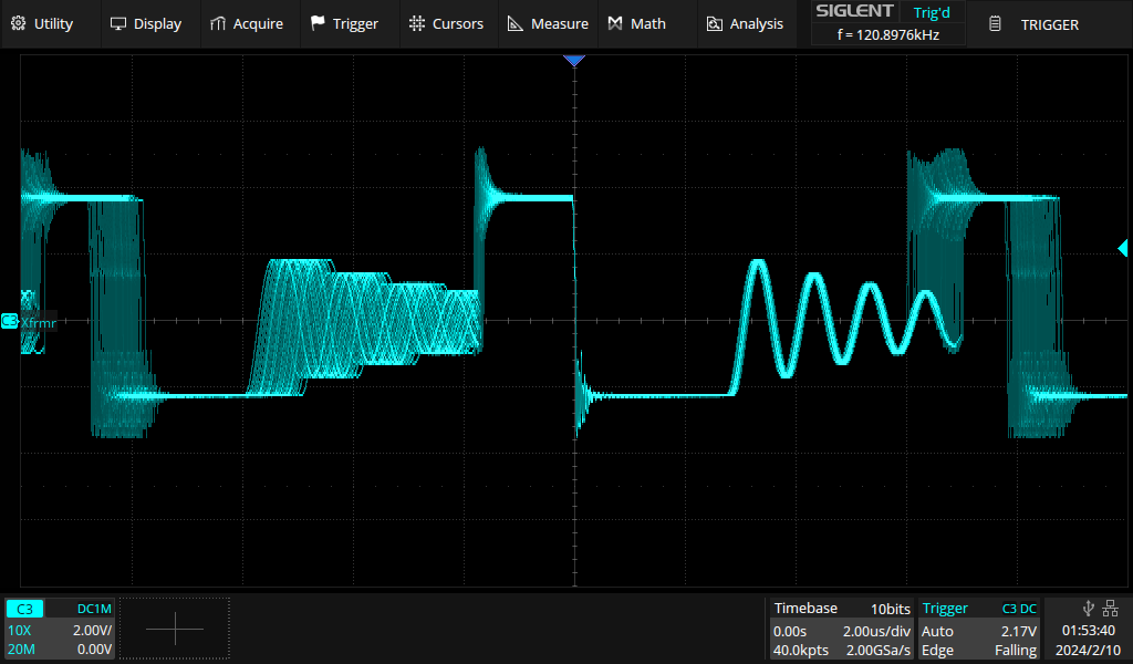
- The supply is supposed to be able to output 0.6A, but it consistently will shut down at 0.27A of load. (Please see attached pictures to see the waveform on the transformer just prior to shutdown).
- The output voltage is inaccurate, it is supplying about 22.3 V at no-load, and decreases markedly with load. It's about 21.85V at the shutdown when loaded to 0.27A.
- The unit will not start up under any load above about 0.18A, it immediately shuts down.
I have imaged the PCB with a thermal camera during operation, nothing is getting hot. Maximum temperatures on the LinkSwitch-HP, output diode, and transformer are no more than 35C with a 25C ambient.
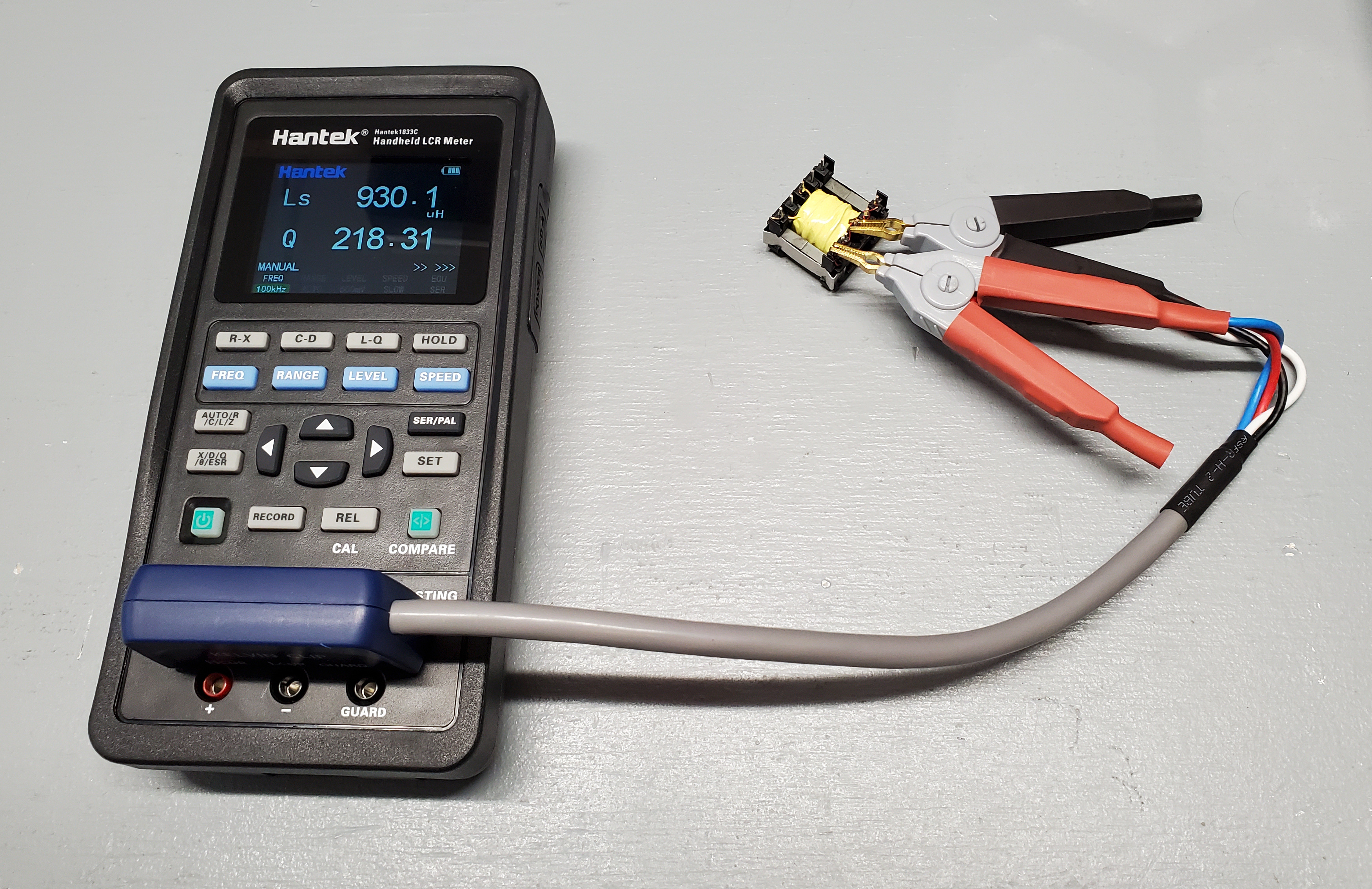
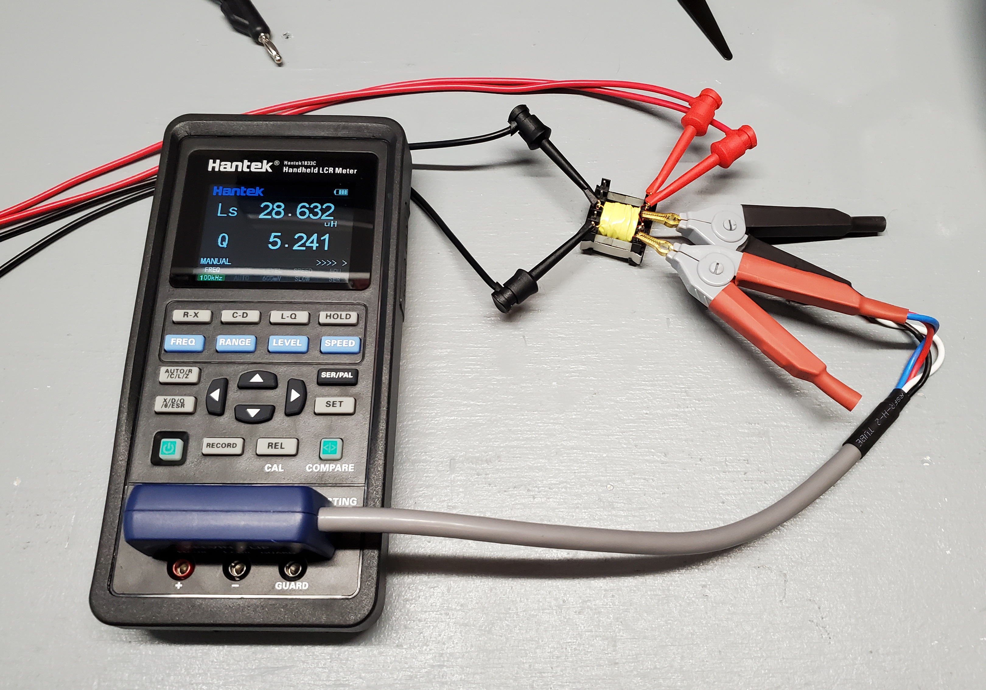
Attached are the PDF files from Pi Expert, including the Design Sheet, Schematic, PCB Layout, Transformer Construction, and BOM. The transformer is hand-wound, but looks to measure very close to the specified readings. Primary inductance is 930 uH, leakage inductance is 28.6 uH. The core that is used has an air gap tuned to an ALg of 490 nH/T^2, as specified in the design document.
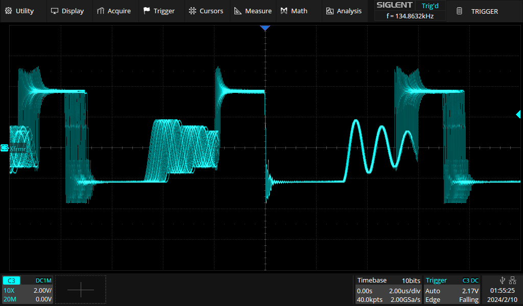
I am at a loss to explain why the unit is shutting down before 1/2 load, but it's very curious to me that as the load increases from zero, the switching frequency increases as well, and the shutdown happens exactly at the point where the switching frequency is supposed to stop increasing and the pulse width is supposed to start increasing instead. The switching frequency at shutdown is right at 136 kHz.
Can to please take a look at the design sheet and see if you have any ideas as to what might be wrong here? I'm at a loss, and perhaps primary-side regulation isn't the best solution for this power supply. I was about to begin another design from scratch based on the TopSwitch instead, but I'd like to understand what is going wrong with this design before I do that.
Files
| Attachment | 大小 |
|---|---|
| Design Sheet exported from Pi Expert | 701.45 KB |
| Schematic exported from Pi Expert | 473.87 KB |
| Transformer Construction exported from Pi Expert | 1.25 MB |
| Recommended PCB Layout exported from Pi Expert | 1.01 MB |
| BOM exported from Pi Expert | 653.71 KB |
| Transformer waveform at no load | 40.94 KB |
| Transformer waveform at 0.25A load | 78.66 KB |
| Transformer waveform at 0.27A load just before shutdown | 76.06 KB |
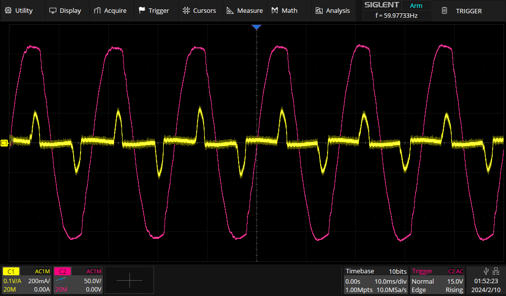
| Input mains current and voltage at 0.25A load | 59.89 KB |
| Measurement of primary winding inductance (all other windings open) | 2.28 MB |
| Measurement of leakage inductance (all other windings shorted) | 1.96 MB |
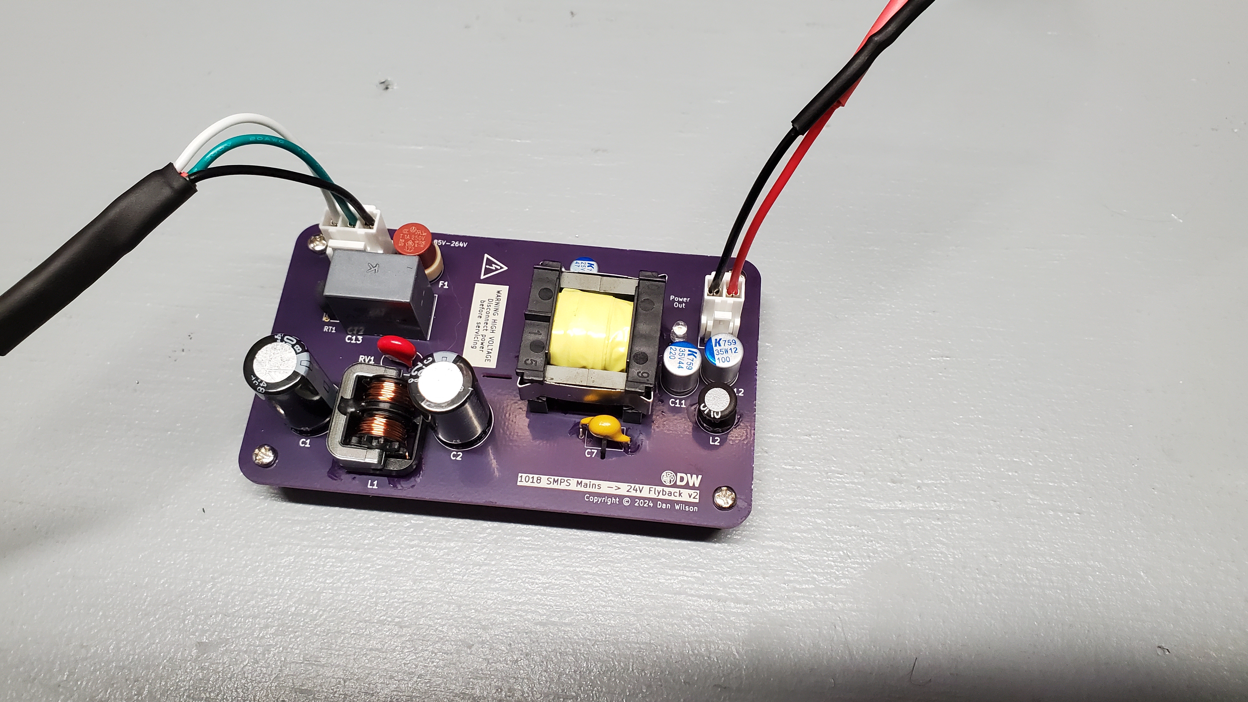
| Assembled top side of PCB | 4.2 MB |
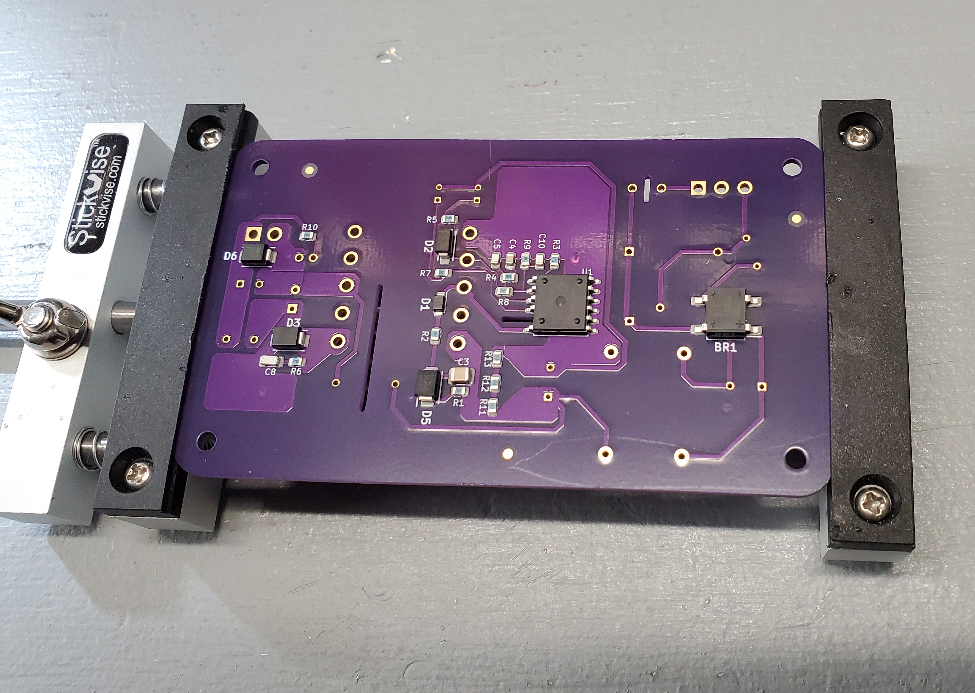
| Assembled bottom side of PCB | 2.24 MB |
评论
Hi,
I am supecting that it could be triggering Output OVP and the reson could be excessive riniging on the FB sense waveform.
I saw that the leakage is very high on this design. One thing that you might want to do is reduce the insulation tape to one layer instead of three layers and that could reduce the leakage inductance. gernerally when you are using split winding techinque you should have Leakage inductance around 1% of the magnetizing inductance.
Another thing that you can try is, use a slow doide on (glass passivated with around 1uS trr) FB sense winding which could also help in suppressing the excessive ringing. Also try changing the primary clamp diode to a glass passivated with around 1uS trr.
Apart from this the transformer waveform that you have attached, can you point to me in the circuit where exactly you have placed your probes.
Also can you capture, PD pin waveform, CP pin waveform and FB pin waveform during the fault condition. also provide the zoom in waveform.
Regarding the output voltage regulation, since this is PSR, you may need little bit of preload at no load conition to maintaing the output voltage with in regulation limits.
Regards,
PI-NANO
Hi PI-Lupin, thank you for responding. I opened a support ticket with technical support and they suggested a few things also.
- The problem may be regulation in that the drop in output voltage may be causing Vfb to fall into the Auto-Restart range. To attempt to validate this, I will be taking some readings on the feedback pin and the voltage divider feedback resistors to compute the current in/out of the feedback pin under various load conditions. This may tell me specifically what protection mechanism may be responsible for the shutdown.
- He also mentioned that the leakage inductance is high. This is because the transformer is hand-wound vice machine-wound, and with hand-winding I cannot get the coils to lay as close together as can be done with machine winding. I may attempt to reduce the tape layers between windings to increase coupling.
- We can change feedback resistors to increase the output voltage and possibly increase margin to the auto-restart voltage.
- The current limit resistor selection can be changed to allow more primary current.
For the transformer waveform pictured in the attachments, this was obtained using an additional single turn of wire on the transformer core that was not connected to anything except the oscilloscope. Thus, the shape of the waveform is accurate, but the absolute values of the voltage in the picture do not correspond to any measurements on the actual board. I can probably measure the drain pin directly and get a similar waveform, or measure the bias winding directly to get the same waveform.
Thank you for the suggestions on the diodes. I will investigate that at as a later troubleshooting step if we still cannot figure out what's happening.
I also have a new design I'm going to try out based on the TinySwitch-4 instead of the LInkSwitch-HP, that design may be more forgiving of the hand-wound transformer and the resulting high leakage inductance.
Thanks again for your suggestions, I will post back when I have some results.
Hi Gents, can you comment on this please? If this is not the correct place for me to get design support, please let me know and point me to where I can get design support for this project.
If I can't find out what happened here, I still have to move my project along, so I will have to go to a flyback controller chip that I've worked with before from Texas Instruments that I know works.