

Related Videos
Unboxing: 15 W Low-Profile Reference Design for 800V AI Data Centers
See how Power Integrations' low profile reference design, DER-1114, enables efficient auxiliary power conversion in 800 VDC AI data centers.

Unboxing: 35 W Multi-output Auxiliary power supply for 800 VDC AI Data Centers (DER-1110)
Discover the DER-1110 reference design, a 35 W multi-output auxiliary power supply optimized for 800 VDC AI data centers. Built around the highly efficient InnoMux™-2 EP flyback switcher IC with...
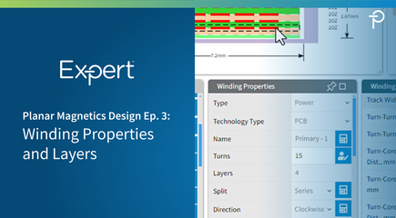
PI Expert Planar Magnetics Design Step-by-Step Ep. 3: Configuring Winding, Via, and Pin Parameters
This overview covers the second step in the planar transformer design process using PI Expert's Magnetics Designer tool. After defining the stack-up, users can refine winding and layer properties such...
PI Expert Planar Magnetics Design Step-by-Step Ep. 4: Optimizing PCB Dimensions and Pin Placement
This overview covers the final step in the planar transformer design process using PI Expert's Magnetics Designer tool. After defining the stack-up and winding parameters, users can optimize the transformer’s form factor by adjusting the pin area, repositioning pins, and refining PCB dimensions. The tutorial explains how parameters such as XP1, XP Left, and XP Right determine the available pin area and can be modified to create a more compact layout.
The video also demonstrates how to move individual pins, adjust pad and hole diameters, and ensure pin placements remain within the defined pin area. Once pin locations are finalized, users can further reduce the PCB footprint by modifying enclosure dimensions, including the XP and EP1 parameters. These steps complete the planar transformer design process and prepare the design for manufacturing export.
PI Expert Planar Magnetics Design Walkthrough
- Ep 4 - Pin Positions and PCB Dimensions
