
1250 V /1750 V GaN Solution Addresses the Need for 800 V Bus Architectures in Power-Hungry AI Data Centers
By Roland Saint-Pierre, VP Product Development, Power Integrations
The rapid adoption of generative AI, driven by power-hungry GPUs, has pushed rack-level power demand from tens of kilowatts just a few years ago to well over 100 kilowatts today—with megawatt-per-rack designs predicted in the near future.
A recent NVIDIA blog states the challenge clearly:
“Delivering this level of power at traditional low voltages, like 54 VDC, is physically and economically impractical.”
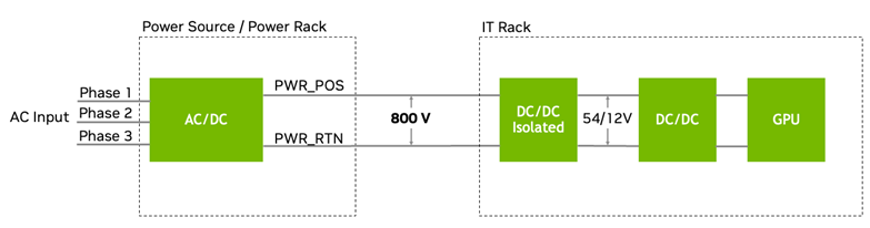
To overcome these limitations, the industry is converging on an 800 VDC bus architecture for next-generation AI data centers—or “AI factories,” as NVIDIA now describes them. This high-voltage approach dramatically improves power delivery efficiency, reduces cable losses, and simplifies rack-level design, paving the way for scalable, cost-effective AI infrastructure.
Key Reasons for 800V DC Adoption
- Higher Power Density and Scalability
Distributing power at 800 VDC dramatically reduces current requirements—for example, from 8,333 A at 48 V to 500 A at 800 V for a 400 kW cabinet. - Improved Energy Efficiency
Higher voltage reduces resistive power losses (I²R losses) during transmission, lowering wasted energy and heat generation. It also simplifies the power path by eliminating multiple AC-to-DC and DC-to-DC conversion stages common in traditional data centers, boosting end-to-end efficiency by 5% or more. - Reduced Infrastructure Costs and Complexity
Lower current means thinner conductors and smaller connectors, cutting copper usage by up to 45% per 1 MW rack. This reduces material costs, simplifies cable management, and frees valuable rack space for additional compute resources. - Enhanced Reliability and Thermal Management
A streamlined architecture with fewer conversion stages reduces potential failure points and lowers waste heat, easing cooling requirements—critical for high-density AI systems.
The proposed 800 V architecture is shown in Figure 1:
Technology Options for 800 VDC Intermediate Bus Conversion
Several approaches exist to step down 800 VDC to intermediate voltages such as 54 V or 12 V for rack-level distribution:
- Silicon Carbide (SiC) Solutions
SiC devices easily handle the 1200 V breakdown voltage required for 800 VDC systems, providing the necessary operating margin. However, SiC is typically limited to lower switching frequencies, which constrains achievable power density compared to GaN-based designs. - Conventional GaN Solutions (650 V to 750 V)
Most commercially available GaN devices are rated for 650 V to 750 V, insufficient for the proposed 800 V architecture. To overcome this, some manufacturers suggest stacked topologies—using two-in-series half-bridges (four 650 V GaN devices total). While this enables high-frequency operation, it introduces significant drawbacks, including control complexity, reliability risks from input voltage imbalance, increased footprint, and higher conduction losses, which reduces efficiency and increasing cost. - High Voltage GaN Solutions (1250 V to 1700 V)
GaN HEMTs built by Power Integrations using its proprietary PowiGaN technology offer a distinct alternative. They enable practical GaN devices rated up to 1700 V, eliminating the need for stacked designs. This simplifies system architecture while delivering high-frequency operation, robust reliability, and superior efficiency—making PowiGaN an ideal solution for 800 V and higher-voltage DC architectures.
PowiGaN-Based IBC Architectures
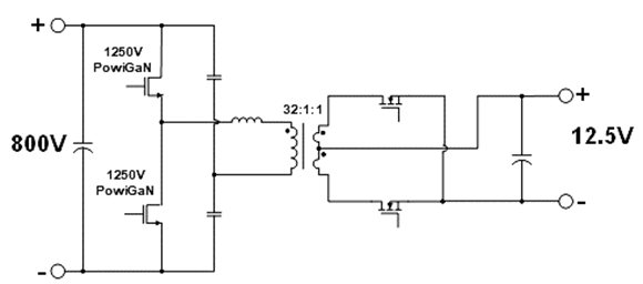
With the 1250 V PowiGaN cascode switch, power supply designers can confidently specify VDS(PEAK) of 1000 V, while maintaining the industry-standard 80% de-rating for reliability. For applications requiring even higher voltages—up to 1360 VDS(PEAK) —the 1700 V PowiGaN cascode switch enables similarly high-efficiency designs at elevated voltage levels.
The proposed structure of the intermediate bus converter (IBC) using PowiGaN is shown in Figure 2:
The advantages of PowiGaN become clear when comparing architectures.
Table 1 summarizes the differences between a 650 V e-mode GaN stacked approach and a single half-bridge LLC design using 1250 V PowiGaN. The PowiGaN solution eliminates complexity, reduces footprint, and improves efficiency.
| Stacked half-bridge LLC with 650 V e-mode GaN | Single half-bridge LLC with 1250 V PowiGaN | |
| Input capacitance imbalance | Yes | No |
| Gate drivers | 4-piece drivers + 3-piece isolated drivers | 2-piece drivers + 1-piece isolated driver |
| Isolated bias supply for driver | 3 pieces | 1 piece |
| Conduction losses with same GaN RDS(ON) | x2 higher losses | — |
| Required GaN RDS(ON) with same efficiency and loss | — | x2 higher RDS(ON) |
Table 1: Comparing a stacked approach with the single half-bridge LLC using 1250 V PowiGaN
Table 2 compares 1250 V PowiGaN with 1200 V SiC MOSFETs, showing that PowiGaN enables higher-frequency LLC operation at similar RDS(ON), delivering superior power density and thermal performance.
| SiC MOSFET | PowiGaN | PowiGaN Value Proposition | |
| Voltage Rating (V) | 1200 | 1250 | Higher BV |
| RDS(ON); mΩ 25 °C | 60 | 60 | Same RDS(ON) |
| QOSS@ 800 V; nC | 180 | 140 | High Frequency |
| LLC Qg; nC | 106 | 45 | Low Drive Losses |
| TD(OFF); ns | 48 | 15 | Low Turn-Off Losses |
Table 2: Comparing 1250 V PowiGaN and 1200 V SiC MOSFETs
Device Reliability and Auxiliary Power Applications
Power Integrations’ 1250 V and 1700 V GaN HEMTs are normally-on, depletion-mode devices implemented in a cascode configuration with a low-voltage silicon MOSFET to achieve normally-off operation—essential for safe system design. Because depletion-mode GaN devices do not require a p-type GaN gate layer, they avoid threshold voltage drift and related instability concerns, ensuring long-term reliability in high-voltage applications.
Beyond the IBC, Power Integrations offers a unique solution for auxiliary power supplies in 800 VDC data centers: the 1700 V PowiGaN InnoMux2-EP IC. This device integrates a 1700 V PowiGaN switch capable of supporting 1000 VDC input, along with primary- and secondary-side control, protection, and safety-rated FluxLink™ feedback. Operating in SR-ZVS mode, the InnoMux-2 IC achieves greater than 90.3% efficiency for a 12 V system output in liquid-cooled, fan-less 800 VDC architectures—ideal for auxiliary rails such as 48 V fans and 12 V standby systems.
Conclusion
The capabilities of 1250 V and 1700 V PowiGaN technology for 800 VDC power architectures are detailed in a new white paper from Power Integrations, published at the 2025 OCP Global Summit in San Jose. These innovations enable high-density, high-efficiency power conversion for next-generation AI data centers, delivering unmatched performance, reliability, and system-level simplicity.