
designing wide input range SMPS with Isolated multiple outputs
Dear Sir, I am already using SMPS with PI device (TINY and DPA Family)
But now I want to combine both range AC & DC, means universal 18 to 265 VAC supply range, and I gone through PIXLS, & I am facing problem for transformer design in the software.
I also referred application note di152, but it doesn't show all design parameter.
So, please support us for this new requirement, as it is wide input range.
Specifications are as mentioned below.
Input range: 18-265VACOutput1: 25VDC@110mAOutput2: -15VDC@30mAOutput1 & Output2 has common Ground1.Output3: 13VDC@35mAOutput4: -13VDC@35mAOutput3 & Output4 has common Ground2.
Ground1 and Ground2 are Isolated from each other, & also isolated from Primary.
suggest me the transformer design as well as schematic design.
I do not want to use bias winding, because EFD12.6 core has 8 pin smd bobbin.
I want to use TINY III Or TINY 4 family.
Your early reply is always appreciate.
댓글
We have designed SMPS design with 4 isolated outputs of 5V/500mA,12V/100mA,24V/100mA,-5V/140mA using PI expert. But with this design 5V output has to be loaded fully then only other outputs works which is absurd. I am attaching the design and also the transformer design which we have used actually. As 16 pin bobbin pin is not available in market so we have used 10-pin bobbin where secondary winding that of 5V is on primary side. And also we have replaced TNY285 from design with TNY267. So can you please suggest me any solutions for this issues.
| 첨부 파일 | 파일 크기 |
|---|---|
| Power supply design by PI.pdf | 190.92 KB |
| Transformer Design.PDF | 33.69 KB |
Do you see any voltage at all on the other outputs when the 5V/500mA output is not loaded?
Yess i can see the voltages on each output but its not according to specs every output voltage is dropped.
Hi,
How do design a wide input(85-270AC/DC) AC-DC converter with two outputs. I fail see option for adding second
output in PIXls.
help solicited
Thanks
You can add multiple outputs when you create a new design.
| 첨부 파일 | 파일 크기 |
|---|---|
| Capture.PNG | 383.34 KB |
Hi,
In PIXls when I create a new design, which section should i use to add multiple secondary outputs?
The option to add additional outputs is at the bottom on the design spreadsheet.
Sorry, this was supposed to be a new toppic, not a comment.
Hi,
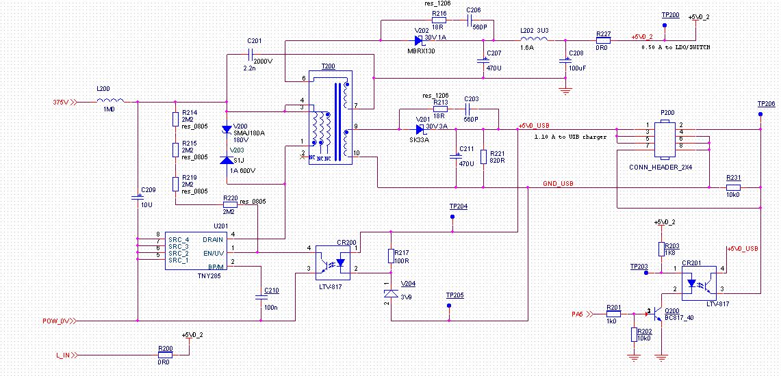
We designed an AC/DC power with an TNY285. It has 2 outputs, 5V/0.5A and an isolated 5V/1.1A. It uses an EE16 size transformer.
It works OK when both outpus are loaded. But if the 0.5A output has only a light load, the output voltage increses to about 7V when the isolated output is loaded with 1A. Simulary, if there is no load, or only light load on the isolated output, the output on the other 5V output drops when loaded. At 400mA the voltage is only 3.5V. The voltage on the isolated output is stable all the time. What can be done to keep both outputs stable? Is it possible in the PI-desiner to simulate a design with varius loads?
Can you send us the PIExpert (.uds) file please? Which output is the primary output? What kind of feedback do you have?
Here are my design and the uds files.
The 1.1A isolated output is the primary.
| 첨부 파일 | 파일 크기 |
|---|---|
| TinySwitch-4_PIDesign6.uds | 371 KB |
| TNY285.JPG | 201.2 KB |
1. C211 is set to 470uF per your schematic. Can you try increasing it to 1200uF?
2. Also, the LTV817 should be connected to the 1A output. Seems like it is connected to the 0.5A output.
3. R203 is 1.8k. Short this resistor and check if your converter regulates.
1. I have tried to increase C211 and there was no difference other than better ripple.
2. The CR200 LTV817 IS connected to the 1.1A oulet.
3. R203 is not in the regulation loop. It is is just a current limiter to the CR201, the 2nd LTV817, that is used to signal between the 2 voltage domanes.
Can you try disconnecting the circuit that comprises of CR201 and Q200 so that only the 5V, 1.1A output is a part of the feedback loop. The idea is to check if the CR200/V204 based control loop which is connected to 5V, 1.1A output is fuctional.
This made no differece. The control loop is functional as the 1,1A output is stable for loads from 0-1A.
The problem is the 0.5A output. For no load on any output, the voltage is 5V but with load it varies a lot. See attached table.
| 첨부 파일 | 파일 크기 |
|---|---|
| 5V supply load.pdf | 66.71 KB |
Please check the winding rotation on the 0.5A output. Can you verify the correct flyback waveform on the 0.5A output?
You can design a TNY power supply with your spects. With Vin as low as the spreadsheet allows to to enter. You design with more POUT that you need. Let say 2 X POUT
Then you implement the circuit in the bewlow link
http://www.powerint.com/node/234
This circuit will allow your TNY power supply to run at very low input voltage. When you have a prototype, check the design for full power at minimum VIN