
LNK6763K - Startup
Hello,
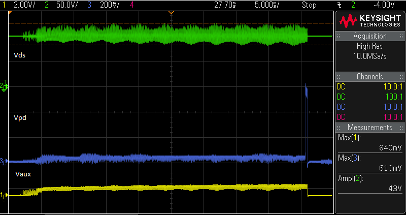
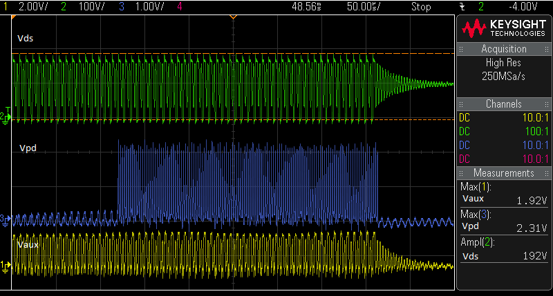
I am doing a startup testing for a LNK6763K based 15W flyback converter. My query is regarding the sudden current shoot-up, which was observed by probing the voltage across resistor at PD pin. The current is rising smoothly at startup, but there is sudden spike of 16.4V every 60ms once. Can you point out the possible reasons behind this?
Quick response would be appreciated.
Thanks,
Sakthivishnu
コメント
Without the information I requested, there's not much I can do to help you with your problem.
Hi,
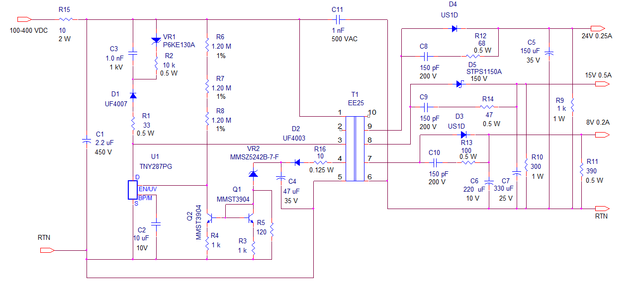
Please find the attached schematic, PI design sheet and waveform details.
Test condition: no load, input voltage sweep: 100Vdc to 200Vdc
Power supply restarts every 1600ms
Looking forward on your comments.
Thanks,
Sakthivishnu
| Attachment | サイズ |
|---|---|
| LinkSwitch-HP_15W_V8.0_95.pdf | 2.55 MB |
| LNK6763K_Schematic.pdf | 105.33 KB |
| SCOPE_287.png | 36.59 KB |
| SCOPE_286.png | 43.88 KB |
First off, the estimated efficiency of this design was way too optimistic at 0.95. I would expect an actual efficiency more on the order of 0.85 or so. To get 0.95 efficiency you would need to use one of our devices with a GaN switch.
Re-run your design with the 0.85 efficiency value and you will get more realistic results. I ran the design using PIXLS and it looks like using a LNK6763K is still possible.
I actually ran the design using PIExpert, and it estimated efficiency at ~79%, possibly because an ultrafast diode is needed at the 24V output because of the high Vinmax, plus the wide input voltage range, and the relatively low output power. It is still possible to use the LNK6763K at this output power (15.1W).
I got more satisfactory results using PIXLS by tricking the input AC voltage to resemble DC input of the proper span, and using a 1000uF filter cap.
I was able to force a design in PIXLS using an EF25 core, which would allow you to use a 3mm margin at the bottom edge of the transformer bobbin, providing enough creepage to enable a safety rated XFMR using triple insulated wire output windings. It would also be necessary to wrap the bottom core of the transformer to get pin-to-core-to-pin creepage spacing between primary and secondary windings. A good EF25 vertical bobbin is available from Taiwan Shulin, Part Number TF-2554
Dear Team,
Could you please share the PIXLS sheet to cross check it.
Thanks.
Here is what I got using PIXLS. The core is somewhat large for the output power, but it does reduce the number of turns needed. I suspect you could do something similar using an EEL19 core by raising the turn count. I think the most expedient way to construct the transformer would be to ignore the instructions and place a single 3mm margin at the bottom of the bobbin to space the primary winding away from the secondary pins - this would be done for each primary layer, as well as the primary bias winding. Secondary windings would be wound using triple insulated wire. As I said previously, you would want to tape wrap the core that goes into the bottom of the bobbin to preserve pin-to-core-to-pin spacing in between the primary and secondary. The PIXLS file I ran is appended. As previously mentioned I tinkered with the AC input voltage and filter cap value to approximate the min and max DC input values.
The efficiency is somewhat low in the case of this design because of the 4:1 DC input span, forcing a low value of VOR in order to meet voltage derating for the primary switch at max input voltage. This forces up the peak primary current as well as the peak output voltage at max DC input and requires the use of an ultrafast rectifier for the 24V output.
| Attachment | サイズ |
|---|---|
| LNKHP_15W_EF25.pdf | 1.29 MB |
I also ran a design in PIXLS using an EE25 core, which is smaller in size than the EF25. Yih Hwa Bobbin Enterprises in Taiwan makes a vertical bobbin EE25 bobbin with an extended "back porch", giving extra safety spacing for the triple insulated secondaries and allowing removal of the tape margins. I suspect that the bottom core of the transformer will still need to be tape wrapped to attain the necessary pin-to-core-to-pin spacing to meet safety. The bobbin catalog number is YW-360.
Hi,
We tried with new design, but the results are same.
Input operating range does not change with the change in Rfb resistor values.
PIXI Sheet was prepared for 85Vdc to 400Vdc but circuit works for 50Vdc to 160Vdc.
Conceptually what else might affect the input operating voltage range other than the feedback resistors.
Thanks.
| Attachment | サイズ |
|---|---|
| LinkSwitch-HP 85 to 400 0.1 EE30_0.pdf | 536.33 KB |
I am assuming that you have such a wide input range for this supply because it is a supervisory supply that runs at the output of a PFC, and is expected to deliver full power whether the PFC is off or on. Please correct me if I'm wrong...
In that case, a more realistic approach would be run the PIXLS spreadsheet using the actual output capacitance of the PFC in question, with the actual input AC voltage range expected.. The power supply is expected to turn on a a pretty low input voltage, so it may encounter input OV shutdown at a correspondingly low input voltage. The may be ways around this problem, but it may require more circuitry to shape the response contour of the voltage sense pin on the LINK-HP. .
Hello,
I am jasvant, co-worker of Mr. Sakthi Vishnu at versa drives. We are working together on this project. I will try to simplify our problem to you.
To answer your question - No, we are not using PFC stage prior to the SMPS. The supply to SMPS is directly DC from a digitally controlled power supply.
We have designed two SMPS using PI expert. The Input operating range being the only difference between the two. First, SMPS is supposed to work from 100-400 Vdc while the other one should work from 200-400 Vdc.
But none of the SMPS is working in the specified input range. We are using the components as suggested by the PI expert generated schematics. I am attaching both the schematic files for your reference.
What could be the reason behind this?
Quick help would be appreciated.
Thanks,
Jasvant
| Attachment | サイズ |
|---|---|
| 100-425 Vdc.pdf | 2.56 MB |
| 200-400 Vdc.pdf | 2.56 MB |
You may have better results using a TinySwitch-4 rather than a Link-HP, as you can program the turn-on voltage directly using a resistor string. I have attached a sample circuit that uses a few additional components to allow primary side regulation, along with a BOM. I have added 10% preload resistors to the outputs, so that the output voltages do not rise out of control if the outputs are unloaded. If you have a reasonable guaranteed minimum load for each output, the preload resistors can be omitted. I will also include a transformer drawing when I have time to generate it.
| Attachment | サイズ |
|---|---|
| TNY4_15W1_100-400VDC_SCH.png | 45.53 KB |
| TNY4_15W1_100_400VDC.pdf | 41.14 KB |
A circuit diagram and a scope picture of the perceived problem would greatly help speed the analysis.