

Zero-Cross Detection accurate only for the negative half cycle
I'm using LNK3307 in 5V 0.5A power supply with zero crossing. I've based my design on the RDK-877 Reference Design Kit.
The zero crossing is only accurate for the negative half cycle of the Ac but triggers early for the positive half cycle. Please see the attached ZC_Osciloscope image.
See attached LNK3307_PSU schematic.
Comments
Hi,
I used HV Differential probes for the AC and passive voltage probes for the ZC. I used the same probes on the RDK-877 and it works fine there.
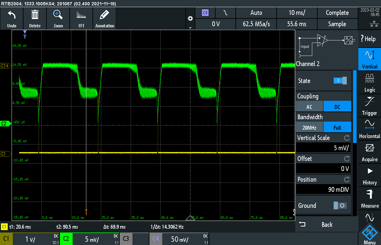
I've attached the PCB layout and probing the mosfet gate. Green is 2N7002 gate and yellow is ZC.Mosfet was measured with Differential probes.
| Attachment | Size |
|---|---|
| layout_1.png (120.83 KB) | 120.83 KB |
| SCR02.PNG (72.09 KB) | 72.09 KB |
Hi latk,
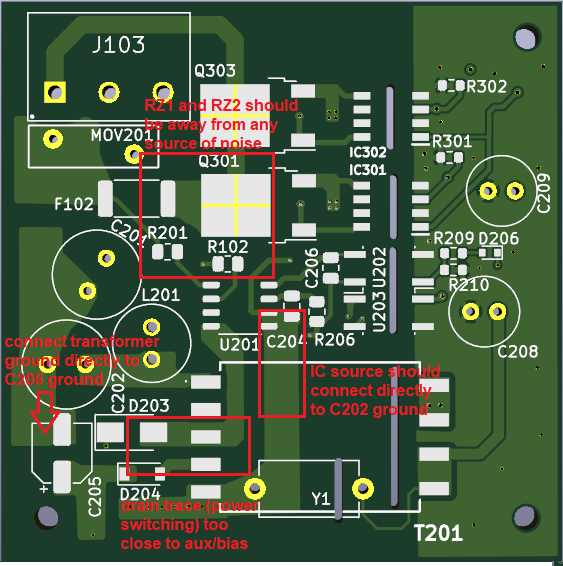
There are some noise concerns because of the layout that may be causing the inaccuracy:
- Ground traces should be star connected to the C202 bulk cap (-) pin
- Drain trace should be as short as possible
- Traces with power switching should be as far as possible from sensitive traces
- Move Q301 and Q302 away from RZ1 and RZ2
- Move snubber and drain trace away from bias/aux
In your waveforms, are there anything connected to the outputs or did you only populate the PSU section?
| Attachment | Size |
|---|---|
| layout notes.png (83.54 KB) | 83.54 KB |
Hi,
Thanks for the feedback.
The design is for a dimmer but the dimmer part is not yet populated during my tests it's just the PSU for now, the only thing connected to the output is a multimeter.
It looks like I have to do another revision of the board taking into account the points you have mentioned and try again.


Hi latk,
A few questions so we could better assist you :
Can you also send your PCB layout?