解决方案查找器 技術支援

LNK304 audible noise

Posted by: zedman on
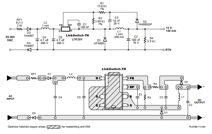
Dear Sir, we would like to use LNK304 as a non isolated power supply in a home automation system's wall switch unit. It's an RF operated remote switch. It should provide max. 40mA to operate the 12V relay and the RF/MCU circuit. I built the circuit from epr48.pdf and put a 3.3V voltage regulator after it, along with a 100nF/100uF combo. I replaced the 1N4005GP to SUF4007 because that was available here. Also I put in a normal 1mH inductor nothing special. (I tried wire wound and normal too). Everything works fine (just the inductor gets warm) but there is a disturbing noise when I switch it on. I figured out the noise source is D2 (the freewheeling diode), and it depends on the load too. If I switch on the relay than the noise gets much lower. Do you have any idea how can I reduce or eliminate this noise? (There will be more than one of these switches in a room so it must be quiet) thanks, Zedman

回應

Submitted by PI-Chekov on 08/19/2008

Hello Zedman

Can you post the schematic? - I want to see which parts could be an issue. On the plus side our reference boards are quiet so there must be a culprit!

Cheers

PI-Chekov

Hi, sorry for the delay I've been out of office. Here is the schematic, hope it helps. thanks, zedman
Submitted by zedman on 08/22/2008
Hi, is the attachment okay? Can you display it? thanks, Zedman
Please Mr. Chekov, should I repost the schematic? Was the attachment OK?
Hello Zedman, thanks for the schematic. Nothing stands out so I suspect it's the inductor. Can you send me a private message so I can get your details and I'll send you one of the 1 mH we use (unless you have an RD131 or EP48 board you can take the inductor from). Datasheet attached for reference. Cheers PI-Chekov
Submitted by zedman on 08/26/2008
Hi, I put on another 1mH in parallel with L1 and now the noise is much lower, when I switch on the load I can't even hear it. But does doubling the inductor value has any impact on the other parts of the circuit? thanks zedman
Submitted by zedman on 08/27/2008
Okay, I'll try it when I get home, thanks!
Submitted by zedman on 08/27/2008
Dear Prasun, I've tried it but unfortunatelly it did not help. The noise is the same as before. Any other ideas? thanks Zedman
Submitted by zedman on 08/28/2008
Inductors sent by Mr.Chekov are still in France, so no chance to try them yet. I am sad.
Submitted by prasun on 08/29/2008
r u sure that with UF 4007 it is also not working...? if its so....then as checkov said, inductor may b issue, but jst try uf4007 as it is a proven design.
Submitted by zedman on 08/31/2008
Finally inductors has been arrived, thanks Mr.Chekov. But it's still the same with the new inductors too. I will try to get UF4007, but the stores here doesn't have it in stock. They have BYV26C, as it's listed in an37.pdf I'll get some and will post the results. What are the impacts of using 2mH inductor? Should I post the PCB ? thanks, Zedman
Submitted by zedman on 09/01/2008
Unfortunately I don't have isolation transformer, nor isolated probes for my scope, but I put it close to the inductor and saw some waveforms. The scope settings were 1us / 0.1V, with 10x probe. Two images without the load and one with.
Submitted by zedman on 09/01/2008
Sorry, I was dumb, 1mH + 1mH in parallel == 0.5mH so not 2mH as I stated before! Now correctly with this around 500uH inductor the noise is much lower. Today I'll try with BYV26C and a 680uH inductor. thanks, zedman
Submitted by zedman on 09/01/2008
No it still doesn't work. It still emits that whispering noise. I replaced D2,D3 to 1N4007 and replaced D1 to BYV26C. And used a coilcraft 1mH inductor from Mr.Chekov. I bought some 680uH and 470uH. With 470uH it's acceptable but still can be heard. I think maybe the PCB should be bad somehow. please help me and lead me out from the trees. thanks Zedman
Submitted by zedman on 09/02/2008
Anyone's there?
Submitted by prasun on 09/02/2008

In reply to by Quintin

its ok...nothing abt being dumb.the good thing is that ur prob is solved, congrats!.
Submitted by zedman on 09/03/2008
So you think using 470uH is OK? The noise is now low enough, but still can be heard if you listen very close (2 cm) to the PCB. But it's acceptable. If you think it's OK than I'll be happy and put the PCB into small pre production. thanks for all the efforts, Zedman
Submitted by PI-Chekov on 09/03/2008

Can you confirm your specification, both input voltage and output voltage and current.

The issue with a low inductor value is the larger di/dt (di/dt=V/L). If the input voltage is high then the current ramp can be fast enough that the peak current rating of the LNK304 is exceeded.

Cheers

PI-Chekov

Submitted by zedman on 09/03/2008
It'll be operating from 220V. The relay needs 12V/30mA, and the RF part consumes around 16mA@3.3V normally and max 30mA@3.3V when transmitting. (Transmit is very short and rare).
Submitted by PI-Chekov on 09/03/2008

I entered your spec into PIXls and 470 uH is marginal to deliver 60 mA, the recommended value being >545 uH (680 uH being the closest standard value). A 1 mH will also work but this is equivalent to designing for an output power of 1.32 W vs 0.72 W. As a result the average switching frequency will be ~30 kHz at full load and ~15 kHz with only the relay load.

I also noticed in your schematic that you have a 220 Ohm resistor in series with the input. For 220 VAC and 0.72 W of output power this should be fine but the DC bus voltage will be a little lower than calculated by the spreadsheet.

I'm still puzzled why you are getting significant audible noise.

Cheers

PI-Chekov

Submitted by zedman on 09/04/2008
With 680uH the noise is still acceptable. Which input stage do you suggest from an47.pdf page 8? Are you sure if you listen the reference design very close (2 cm) it's quiet? thanks, zedman
Submitted by zedman on 09/04/2008
I noticed something strange! At home I have a protected plug near by the PC where I was tested the circuit. Since the noise level was acceptable I decided to show it to my collegue at the office. BUT here with the 470uH the noise as loud as at home with the 1mH! What should I measure / check / do now?
Submitted by zedman on 09/04/2008
This is the current schematic, I removed some optional parts, just to make sure they don't cause any noise. I tried with 470uH, 680uH and 1mH from Mr.Chekov too but with the smaller L1 the noise gets a bit smaller. I also tried to remove R3 but nothing changed. Do you have any idea? Can I measure something? Do you want me to check the freq of the noise somehow?
Submitted by zedman on 09/06/2008
So, I completely rebuilt the PCB (just the PSU part) to a test PCB according strictly to epr48.pdf. Altough there's a small bug in the pdf, the schematic does not contain C7 capacitor while the PCB does. It doesn't matter in my issue because it's for non resistive loads as I read. L1 is now non wire wound 680uH and L2 is a non wire wound 1mH. D1 is a UF4007 D2,D3,D4 is a 1N4007. Now it's we can say silent. Don't ask why. I don't know. I just hope if I design a new PCB for it, it won't fail. thanks, Zedman
Submitted by PI-Chekov on 09/09/2008

Just spotted that D2 is a 1N4007. This should be a UF4007, ie Ultra-fast recovery. This diode has the full input voltage impressed across it each switching cycle when the LinkSwitch-TN turns on.

Cheers

PI-Chekov

Submitted by zedman on 09/11/2008
Damn, yes, I left it 1N4007 on that schematic, but on the newly built PCB it's UF4007. Thanks, Zedman
Submitted by zedman on 09/12/2008
I rebuilt the PCB again because I designed a new PCB including the RF part, and made it smaller. The PCB I built on a test panel was as I mentoined silent. But this one I made from the same parts (I should have used SMD parts because size is factor) does emits that noise. I don't see difference between the two PCBs except the placements of the parts. I am stuck with this. I do not have more ideas. thanks, Zedman
Submitted by chauhan.vision on 04/06/2016

Hi Zedman , 

did you found any solution for the same. i am also facing the same problem. i followed AN-37. for the the output 12V @ 160mA . used inductor Lin = 470uH and output inductor L = 1.5 mH. feedback diode is 1N4007 and also tried with UF 4007.  Freewheel diode is BYV26C.

do anybody figured out whats the problem here ? 

Regards

Pradeep


Attachment 大小
175-48069 (1).pdf (327.02 KB) 327.02 KB
Submitted by Alex Shabanov on 04/07/2016

Any troubles (2 yrs of exploatation). Yes SOME whispering noise is audible as well, when you only put your ear close to inductor (2..3 cm). But I hope it is not an issue for me for my cooler gives much more noice to hear... If you want I'll share my PCB design here.

Submitted by Alex Shabanov on 04/08/2016

In reply to by chauhan.vision

Hi Pradeep! 

Here are three files schematic and PCB (both picture and source file). There is an area on PCB (at the bottom of a diagram) you do not need to fill with components (the thermo relay circuit cuts off LED string when heatsink's temperature becomes too high to operate). All the rest is the low power non isolated ACDC converter itself. Here we have about twenty specimens run quietly and happily for more than two yrs so far. )) Have fun!

Alex.

Attachment 大小
schematic_diagram (58.67 KB) 58.67 KB
pcb_diagram_picture (148.73 KB) 148.73 KB
pcb_sprint_layout_60_source_file (12.54 KB) 12.54 KB
Submitted by chauhan.vision on 04/08/2016

In reply to by Alex Shabanov

Thanks Alex. 

Submitted by Alex Shabanov on 04/12/2016

into your noisy inductor. Take a disposable injector of 5 cm^3, pull out its piston, drop your inductor into empty barrel, pour isolating lacquer into the barrel (acrylic for instance)... Well, take a look at the picture for my Eng. is not good enough to explain the process distinctly... ))

Well, keep the piston pulled out for a couple of minutes (position #8). Then release, remove the cap (red), carefully push the gases emitted out from the barrel by pushing the piston slowly (in order not to pull out the lacquer - gases only), then put the cap onto the barrel's hole, then repeat vacuum treatment again. Do the cycle described several times. In the end pull out the piston, pull your vacuum impregnated inductor out from the barrel with a tweezers. Pour the lacquer out from the injector's barrel back into its can. Put the inductor into warm place and dry it carefully. Then drop it into your device. Your quiet happiness will come and will never go away. ))


Attachment 大小
vacuum_impregnation.PNG (21.4 KB) 21.4 KB
Submitted by PI-NANO on 04/25/2016

In reply to by chauhan.vision

Hi Pradeep,

Is your problem resolved? If not can you share your schematic and PIexpert/Pixls design file?

Can you also post it as a seperate question, since this post belongs to someone else?

Regards,

PI-NANO

Hi PI-NANO,

my problem is resolved, just made on change in the design. observed  that , when i output inductor , output capacitor and feedback diode. at a distance, there is no noise. made 3 boards and all working fine. dont k ow why but its working good for me. 

Thanks all for the help. 

Submitted by PI-NANO on 05/10/2016

In reply to by chauhan.vision

Hi,

That's good to hear that your issue resolved. However inorder to understand what was causing the issue in the first place, if you can send the Pixls design file, schematic, and PCB layout, I can review the design.

Regards,

PI-NANO