
TOP258GN goes in shutdown mode just after mains power on
Hello All,
I have an Edwards nXDS pump controller. There is an onboard SMPS based on the TOP258GN switch. Due to a power surge, TOP258GN was burnt out. I replaced this switch and two more doubtful components: a 2M ohm resistor connected to the monitor pin and a 47 μF capacitor connected to the control pin.
Now SMPS goes into shutdown mode just after powering on.
Secondary side voltage: +/-23V and +17V
Feedback Section: I have checked feedback circuits and not found any abnormalities.
Secondary side: There is no shortage on the secondary side since I connected an external +/-23V DC to the secondary side, and the system works. So it's clear the problem is on the primary side.
I have one working board and compared both boards. I checked the voltage on every node and found it equal, except for the control pin.
Control pin voltage on the working board: 5.8V DC
Control pin voltage on the faulty Board: 5.4V DC
I checked and found that the diodes and capacitors associated with the auxiliary winding are good.
I am unable to find out the cause of the lower control pin voltage and shutdown of the TOP258GN switch.
Any help would be appreciated.
Thanking you,
Regards,
Vijay
댓글
Hi Tommy,
Thank you for your valuable response.
I forgot to mention the series resistor of 6.8R. According to your attached image, it is C10, actually. Sorry for that.
I do not have a schematic of this design. I measured the input/output voltage on the working board, as given below.
Input: 230VAC, Output: +/-23V DC, 17V DC (23V is bipolar and 17V is only positive).
Faulty board - Input: 230VAC,
Drain-Source Voltage:310VDC,
Voltage at Monitor Pin: 2.9V
Voltage at Control Pin: 5.4V
I checked the optocoupler and TL431; both are working.
I took the help of the attached datasheet (Fig-41).
I am unable to diagnose which component is responsible for the shutdown condition.
Thank you for your support.
Regards,
Vijay
| 첨부 파일 | 파일 크기 |
|---|---|
| topswitch-hx_family_datasheet_0.pdf (3.9 MB) | 3.9 MB |
Hi Vijay,
Good day and I hope you're doing well.
For the drain-source voltage in the oscilloscope, is the TOPSwitch-HX device switching, or is the waveform just showing a flat DC voltage (310 VDC)?
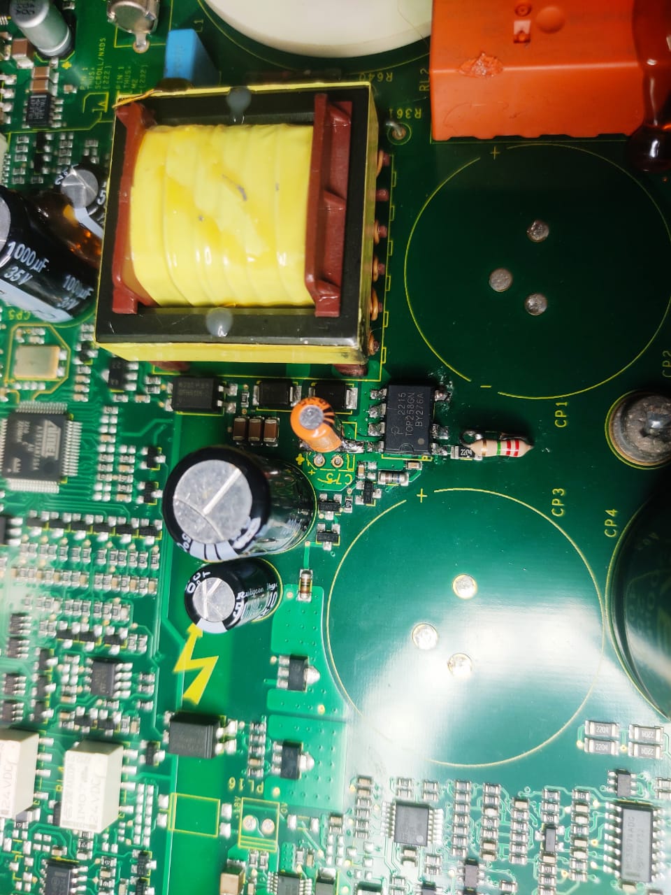
If the TOP258GN is not switching, I suggest replacing the C pin capacitor (highlighted in the attached image) with a 100 nF / 50 V. To verify if this is indeed the C pin capacitor, I suggest doing a continuity test first using a DMM on the traces.
Thank you and looking forward to the results.
Best regards,
Tommy
| 첨부 파일 | 파일 크기 |
|---|---|
| C pin cap.png (791.96 KB) | 791.96 KB |
Hi Tommy,
Thank you for your response. It is a little late in reply, since I was out of the station.
Vds is flat DC. I replaced the new 100nF capacitor, but there was no change in status.
I conducted an experiment to check the protection feature on the control pin by removing the 47uF capacitor, which allowed the control voltage swing below and above 4.8V,
and observed that the switch (TOP258GN) enters the restart loop instead of shutdown mode.
Unable to find out the cause of lower control voltage(5.4v), but it should be 5.8v(measured in the working board).
Thanking you,
With regards,
Vijay
Hello Vijay,
It's okay. I hope you're doing fine.
Unfortunately, it is hard to troubleshoot the design without its actual schematic diagram, PCB layout, and bill of materials. Maybe you could reach out and ask the manufacturer of the board (Edwards nXDS pump controller) about this information so we can further review the design.
Thanks for sharing that replacing the SMD capacitor with a new 100 nF has no impact.
Below are several recommendations to be able to identify the reasons why the TOP258GN is triggering its auto-restart function:
- I would recommend checking each diode of the circuit, especially the output rectifier diodes, by using a DMM to see if they are still functional. Maybe there's a diode that got shorted during the power surge.
- Verify if the output rails are not shorted. A shorted output will result in the TOP258GN triggering auto-restart during startup.
- Replace the optocoupler of the circuit. It is possible that the optocoupler was damaged during the power surge, preventing it from transferring the necessary current feedback to maintain proper output regulation. If the TOP258GN doesn't receive any feedback information during startup from the secondary side through the optocoupler, the IC will interpret it as open-loop and will trigger auto-restart.
- Using an oscilloscope, you can probe and monitor the output voltage if it is rising to its specified voltage.
- Verify the auxiliary bias voltage across bias capacitor. I'm referring to capacitor C10 if we are using figure 41 of the TOPSwitch-HX datasheet as a temporary reference. If the voltage across the bias capacitor (C10) exceeds 20 V, it will inject current to the M pin and trigger auto-restart.
- Removed the components tied to the M pin and shorting the M pin directly to the SOURCE pin to disable its functionality. I'm referring to resistors R3, R4, R5, and VR2 if we are using figure 41 of the TOPSwitch-HX datasheet as a temporary reference. This will allow us to verify if the cause of the auto-restart is related to M pin functionality, like primary output OVP and line OVP and UVP.
I hope that the above recommendation helps. Let me know the result of your testing and i one of the recommendations above resolves the issue.
Thank you and I wish you a great day ahead!
Best regards,
Tommy
Hi Tommy,
Thank you for your valuable time and suggestions.
Now it's working in active mode.
When I replaced the optocoupler, it worked.
Note: It's surprising that I checked the old optocoupler outside the board by wiring it on a breadboard. It is working. Perhaps it has been degraded and no longer meets the system requirements.
Thank you once again :)
Regards
Vijay
Hello Vijay,
You're always welcome. Great to hear that the board is now working. Good job!
If you need further help or have any more questions or concerns, feel free to submit a new inquiry/request through this forum or through our support page, PowerPros Online Support. We are more than happy to assist, guide, and answer all your queries.
Thanks as well for choosing Power Integrations. Have a great day and a nice week ahead!
Best regards,
Tommy
Hello Vijay,
Good day and thank you for choosing Power Integrations.
Since you point out that the C pin voltage only reaches 5.4 V on the faulty board, I believe that the C pin capacitor (not the 47 uF) of the TOP258GN was also damaged when the power surge happened. I recommend changing this C pin capacitor as well with a 100 nF value. I highlighted the C pin capacitor in the attached image for your reference. It is an SMD capacitor that is directly connected between the C and the SOURCE pins.
Additionally, do you know the complete input and output specification of the flyback design? If so, could you share it with us? I would also appreciate it if you could share the schematic diagram of the design as well so we can check.
Thank you and looking forward to the result of changing the C pin capacitor.
Best regards,
Tommy