

SMPS with LNK6769E and EE35 not working
Hello
I am making a SMPS with 3x100V, 0.17A and 6.2V, 5A output with PI Expert Online.
The three 100 volt outputs are connected in series,
but I only get about 3-4 V output.
Help is received with thanks.
Comments
Dear Sir, thanks for your reply. I have attached the schematic.
I have successfully made some circuits with TinySwitch-4 and with InnoSwitch-EP successfully, but this circuits I can not get to work.
| Attachment | Size |
|---|---|
| Screendump.jpg (57.33 KB) | 57.33 KB |
| LinkSwitch-HP_3X100V_0.17A_6.2V_5A_EE35.pdf (2.63 MB) | 2.63 MB |
| LinkSwitch-HP_3X100V_0.17A_6.2V_5A_EE35.uds.zip (26.51 KB) | 26.51 KB |
Hi Amigafan,
I suggest you need to fix first your main output which is 6V. Then you work through other output. You may remove the rectifier of three 100V output so debugging will be easier. Also, make sure of the start and finish of each winding of your transformer. Then we need to probe feedback, BP and Vds pin to check what is wrong with your circuit.
Regards
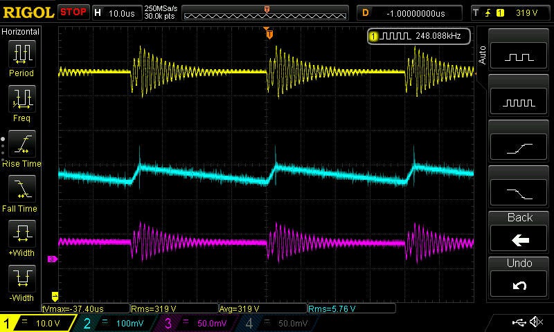
Hi, I have remove the three 100V output rectifier and connected my scope. Yellow probe is connected to D, blue probe to BP and red probe to FB. I hope that it will be of some help.
The three 100V outputs are connected in series to achieve 300V. Is that a problem?
By the way, I have replaced D1 with FR357.
Br Amigafan
| Attachment | Size |
|---|---|
| Measurements of SMPS (96.22 KB) | 96.22 KB |
| Measurements of SMPS (92.04 KB) | 92.04 KB |
Hi Amigfan,
There should not be any problem with 100V in series. Do you really need the 100V? Why not just make a single winding for 300V?
Removing the three 100V is just for easy debugging. Make your circuit as simple as you can and add the additional circuit as you make progress. Just follow the schematic and you should be just fine. Double check also the polarity of each winding as it wouldn't work if one of the termination is wrong. Then run also double check on the polarity of other devices as it already switching.
Hi
My experience with one winding for 300V output is not good. The secondary side capacitor does not get fully charged before the device restarts.
I think the problem lies in the transformer, I will investigate it further.
Thank you for your help.
Regards


HI Amigafan,
Can you send your schematic in jpeg?
Can't open it here.
Also you may want to check your design on our online design tool below.
https://piexpertonline.power.com/site/login
Regards.