

Input electrolytic cap heating up
Hi there,
I've implemented a small PSU incorporating the TNY285 as designed by PI-expert 9.1.6.3 and so far the supply seems to to be operating as expected on the prototype.
I could not source the HV electrolytic capacitors as stated in the BOM, specifically C2, and so have used capacitors by Nichicon instead, UPW2G100MHD, 10uF 400V Low ESR.
A while after power-up C2 which supplies the transformer and TNY switcher directly is running warm which I do not like. The power supply is not under a significant load, probably less than 10% of full design load. Input voltage is approximately 220VAC.
1. Has anyone noticed a similar issue on their designs?
2. If so, what was the cause and how did you solve it?
3. Would PI please forward me a datasheet of the original capacitor as specified in the BOM as I cannot seem to find a document anywhere on the internet for it: United Chemi-Con EKMX400VB10RM10X20LL.
Any assistance appreciated, thanks.
Comments
Hi PI-Mallora, thanks for coming back to me.
Schematics of mains input and switcher attached.
The polarity of the cap within the PCB is correct, an incorrectly populated part would have resulted in an explosion by now!
Would a capacitor with a higher ripple current rating be more appropriate?
Thanks!
| Attachment | Size |
|---|---|
| Switcher schematic (47.75 KB) | 47.75 KB |
| Mains input filter (35.76 KB) | 35.76 KB |
Hi GADV1975,
What is your output power? I assume 10-15W? Is capacitor heating up consistent with all your units?
Higher ripple current means higher ESR/higher power loss so it is better to use lower ripple current. Doing two electrolytic caps in parallel is good reducing the ESR by half if you have the luxury of space and cost. If your total power is around 10W-15W, use two 10uF capacitor in parallel for C26 or a single low ESR 22uf/400V. You can also just short L7 to save cost, if you need additional differential inductance for EMI, just increase L8 inductance. Thanks.
Hi PI,
Output poewr is much smaller, around 5W to 6W.
Ive only built one board, I'm reluctant to build additional and potentially waste parts on it.
I have removed the 10uF cap and used 2 of the 6u8 caps, which are high-ripple current tolerant parts, in parallel. They also heat up!
Is there a chance that the inductance of the primary winding of the transformer is too low thus causing much higher than normal currents during switching by the TNY285?
I also want to try and understand the charging effect from the diode bridge, perhaps that inrush current is too much. Perhaps more inductance in L7 will make a difference?
Too many questions, not enough answers! This issue is threatening our project delivery... I hope I don't have to reosrt to a linear supply instead.
Any (fast) assistance appreciated as we're now on a critical project path.
Thanks!
Hi GADV1975,
Inrush due to start-up can cause your fuse to open but not cause the capacitor to heat up, the common practice is putting a series resistor after the fuse typically 3.3R or 4.7R with your output power. It will also help you pass surge requirement.
Lower primary inductance means higher di/dt for the same voltage creating higher frequency voltage ripple on the capacitor. Adding ceramic capacitor in parallel with e-cap helps to filter high frequency ripple.
L7 and L8 is for EMI compliance but L8 is enough, you can just short L7.
Can you probe the voltage across C26 and show me the waveform so we can have a clue what is happening?
Building 2-3 prototype is basically a good practice since you can verify the consistency of your design. Sometimes we are seeing problem at one unit but not on the other one which makes it easier to debug.
Hi PI-Mallora,
Thank you for the advice regarding the inrush resistor, I will implement in an updated version of the board.
I have added a 100nF 400V directly across the transformer and TNY switcher. C26 now consists of 2 x 6u8 400V electrolytics and 100nF 400V Wima. The 6u8 caps are high ripple current types. L7 has been shorted out. No other changes implemented.
I've reduced the value of C27 on BP/M from 10uF to 1uF in order to limit the primary current during switching. Is my understanding of the functionality of this component correct?
According to the datasheet, the current switching through the transformer is terminated once the current limit is reached. It then takes an additional 150ns for the circuit to react in switching the MOSFET off. If the inductance of the transformer is too low, the di/dt is going to be so fast that the transformer will probably be saturated by the time the current limit is reached and the switching cycle terminated. A saturated transformer is a disaster scenario as it then becomes effectively a low-value resistor. Could this be what's happening in my circuit, thus causing a large ripple current in C26, and thus heating?
In addition, I notice that the transformer runs slightly warm as well, nothing like the capacitor, and the loading on the SMPS output is very light.
I suspect transformer saturation is the issue here.
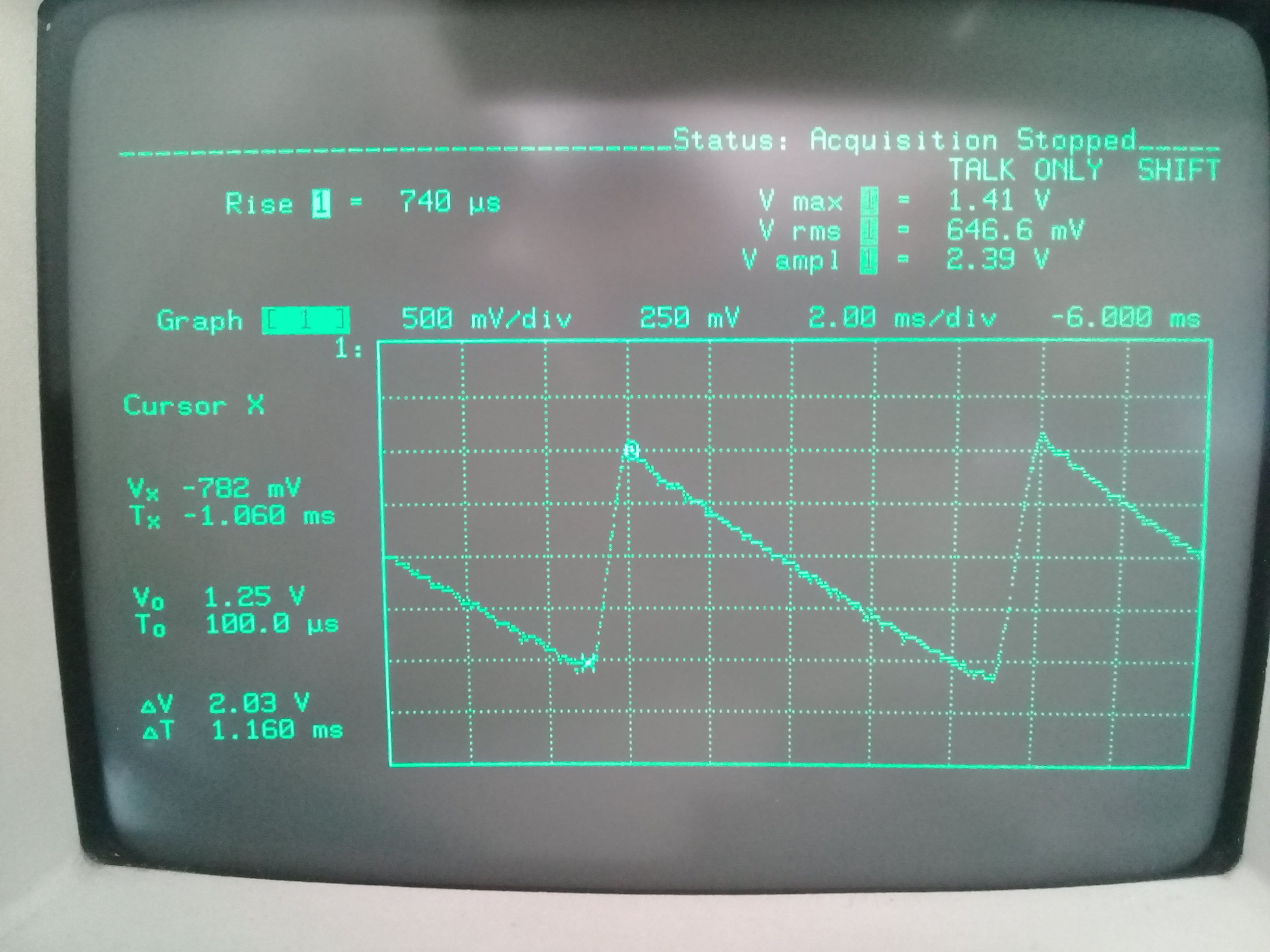
I've included a photo of my scope screen (don't laugh, I have an old scope) showing the ripple across C26. Probe is AC coupled, timing and voltages shown in the picture.
Some additional information regarding the circuitry on the output of the transofrmer: C16 and C21 in my schematic from the above post are not super low ESR caps. Their ESR is about 0.26R, is this likely to cause problems with the circuit operation?
Thanks again for coming back to me.
| Attachment | Size |
|---|---|
| Ripple across C26 that gets warm.jpg (1.8 MB) | 1.8 MB |
Hi GADV1975,
Did you use PIExpert tool to design your power supply? If you use the recommended inductance and all other parameters like BP cap, controller size etc, your power supply should be running good. Can you share your PIExpert design output file?
You are correct on understanding how it operates on switch termination based on transformer current.
HI PI-M,
Yes, I used PI Expert to design the circuit. I only adjusted the outputs, all other settings left at default.
Design file attached.
This morning I built up another power supply of the same design on a new PCB, only the power supply built.
I ran the supply for about 10minutes with no load at all, 231Vac input. No heating of the transformer or capacitor noticed.
I applied a 120R load resistor to the 17V output and let it run for another 15minutes. I noticed that the transformer and capacitor were starting to heatup.
I've added a 150R resistor to the 12V output, and left it to run for several minutes.
The transformer and capacitor are now hot.
This certainly points to an issue with the design or construction of the transformer, what else could it be?
I will run the design file again and select the next two larger cores and investigate having these made up.
The system incorporating the power supply will work in ambient temperatures up to 55deg C, so I really do not wish these components to be warm at room temperature.
Thanks!
| Attachment | Size |
|---|---|
| TinySwitch-4_TNY285_XformerShield_17Vat250mA_12Vat200mA.uds (621.5 KB) | 621.5 KB |
Hi GADV1975,
I checked your PI Expert design and I can't find any errors or warnings.
Can you tell me your measured temperature of the components? At room temperature full load conditions, 70°C transformer temparature is normal. For capacitors around 60°C is fine. If you project that to 55°C, you still have margin since transformer temp limit is usually 120°C while capacitor temp ratings is usually 105°C.
It is your option to use bigger cores to decrease transformer temperature since you can use bigger wire gauge and you have bigger area for heat dissipation. For capacitor you can use 125°C rated capacitors. Thanks.
HI Pi-M,
Thanks for the response and for checking my design out.
I have made up a new design with larger core transformers EE16 and EE19 with the same switcher and am getting these made up to evaluate.
While what you say is true regarding the heat tolerance of the capacitors and transformer, I would prefer, from a realiabilty perspective, to have these components running cooler at room temperature. At this stage we don't know exactly what mechanism is in operation to cause the heating so that's why I'm getting additional transformers made to be able to conclusively close this issue.
The other point which I considered during the design of the new transformers was the input voltage range: the transformers presently in operation are required to handle a large input voltage span of 85V to 265V. 230V is towards the high end of the range and perhaps this is a cause for heating due to mild core saturation. I will run the same boards at 120V and see if the same heating occurs.
I've designed the new transformers to operate from 180V instead, so this requirement and the larger core should hopefully result in cooler operation.
I will keep this thread updated of my observations moving forward until the issue is finally resolved, perhaps others may benefit from the information.
Updated designs attached.
Thanks!
| Attachment | Size |
|---|---|
| TNY285_XformerShield_Core_17Vat250mA_12Vat250mA EE16.uds (1.04 MB) | 1.04 MB |
| TNY285_XformerShield_Core_17Vat250mA_12Vat250mA EE19.uds (770 KB) | 770 KB |
HI PI-M,
I have a query: in your experience of these designs, have you ever noticed input electrolytic caps heating up? If so, how hot would they typically get, and under what load and input conditions?
As this is my first time experience using a PI switcher, I'm not sure what normal circuit opertion is meant to be!
Thanks!
Hi GADV1975,
The heating element of capacitor is due to ESR so the lower the ESR of the capacitor the better. The rule of thumb is every 10°C increase in capacitors temp, its lifespan is decreasing by 50%. Typical life calculation of the capacitor is using Arrhenius Law of Chemical Activity. You can google that if you want to know more about it.
In general, <20° temp rise from ambient temp is good for input electrolytic cap, for output it is usually higher due to higher current so <30°C temp rise from ambient temp is good.
Regarding the use of capacitor on a power supply design, it is no different from other vendors.
Hi Pi-M,
Thanks for the information regarding the caps. Yes, it's been my suspicion that the ripple current trhough the caps will cause heating. The question has always been what's behind the high ripple current!
I initially thought that the transformer could be starting to saturate, so I had some new transformers made on bigger cores, EE16 and EE20 which I integrated into a test circuit board. The capacitor heated with both of them!!
The only other components that I did not check until yesterday were the catch TVS and diode across the primary. I removed them from the circuit and this seemed to stop or slow the capacitor from heating up. I'm going to look into these components more closely as these two are the only other possible source of high ripple currents out of the capacitor. I suspect that the series reverse diode is leaking during the FET-ON state.
I'll report back with any findings, but I suspect this is the cause of the problem!!
The latest observations in this saga:
I've checked the switching waveforms across the MOSFET and the circuit is showing classic discontinuous mode operation. According to a few app notes, this mode of operation leads to higher ripple currents which wiould logically explain why the cap heating up.
I thought that the series diode with the TVS was leaking, so I replaced the UF4007 with a 1N4937 instead. No change, cap runs hot.
Disconnecting the clamp diodes across the transformer primary and the capacitor STOPS getting hot.
I cannot find an explanation for this behaviour!
So, why does the capacitor run warm with a 110V TVS across the primary?
I've now connected two TVS diodes (P6KE110 and P6K130) in series and put them back in circuit. The capacitor is NOT getting hot.
Can someone explain what's going on here please? There must be a reasonable explanation for this!
HI,
I have resolved the mysterious issue of the capactior heating up.
The heating is caused by the heating of the track leading from the TNY device outputs to the capacitor negative terminal. In addition to this heatsource, there are resistors related to a different part of the circuit that sit above the copper track leading to the positive terminal of the same cap. These resistors are also generating heat into the PCB material and the track. All this heat is finding its way into the capacitor which, coupled with the heat generated internally by ripple currents, add up to a warm capacitor. Placing the capacitor off the board on the bottom side disconnects the heat sources from the cap, and it runs much cooler.
I'm also going to add a 100nF 400V PP capacitor in parallel with the electrolytic to help with peak current delivery during switch on of the FET and place 400ohms across the 12V output of the supply as a minimum of 15% load to that supply which drives a relay and small motorised valve which are not always operating.
So lots of lessons and theory learned in the process.
I think that this issue is now resolved and a revised board layout is necessary.
Thanks for the asistance to date.
Hi GADV1975,
Nice to hear that. Thanks for your perseverance and finally you find out the real problem. It is really hard on my side finding the problem when I can't physically see and check your board. Yes it is really alot of lessons learned and can be our guide on future projects. Wish you the success of your project. Good job. Congrats.


Hi GADV1975,
Thank you for using Power Integrations' part.
Can you share your PI Expert design output? You shouldn't have problem with the one you are using from Nichicon. Can you share how high is the thermals? Wrong polarity insertion is one of the possible cause of heating. Voltage stress is another one but you are using 400V with only 220Vac input so it is unlikely. ESR is also ok. You can also check your input rectification, AC component can also make it heat-up. Thanks.