

Vds-on too high
VDrain is by far too high in ON state (around 80V), moreover after around 1 minute under moderate load LNK363 goes in thermal protection.
Attached you can find the PCB and the design performed with PI Expert 9.
Some more picture attached (Vreference: Vsource on primary side, RTN on secondary side):
SDS00003: CH1 Vdrain, CH2 cathode D1. Vd On is very short and high. When Vd switches a wide ringing can be seen, no steady state is reached.
SDS00004: CH1 Vdrain, CH2 cathode D1. Same view, timescale 100us/div.
SDS00005: CH1 Vdrain, CH2 cathode D1. Same view, timescale 500ns/div.
SDS00009: CH1 Vdrain, CH2 V BP. V BP = 5.60 V (see cursor measure).
SDS00008: CH1 Vdrain, CH2 V BP. Same view, timescale 10us/div.
SDS00007: CH1 Vdrain, CH2 V FB.
SDS00006: CH1 Vdrain, CH2 V FB. Same view, timescale 250ns/div.
SDS00002: CH1 anode D2, CH2 cathode D2.
SDS00001: CH1 anode D2, CH2 cathode D2. Traces not aligned. CH2 2V/div, timescale 10 ns/div.
Three questions:
a) Why is VD On so high and its duration so short?
b) Why is ringing so wide?
c) Why thermal protection at such a moderate load (I think it is related to a))?
Thank you in advance for any suggestion you can provide me.
Comments
Thank you Terry for answering.
Answesr to your questions follow.
Moreover I rechecked all solders: something improved, but the basic behaviour remains. I attach new snapshots, please consider these new ones. Now my answers:
1.: Oscilloscope sampling rate. 10-250ns/div: 500 Msamples/s, 500ns/div: 250 Msamples/s, 2.5-10us/div: 100 Msamples/s, 100us/div: 5 Msamples/s. Oscilloscope: Siglent SDS1102CML. 100x probes, bandwidth 100MHz
2. In this new session I had V VR1=348-368V. I tested two conditions:
+ lightload: I RF1 = 8.3mA, I D2 = 47.4mA (corresponding to the original session conditions)
+ medium load I RF1 = 17mA rising to 19mA, then automatic shutdown, I D2 = 120mA
The situation was better, because V Drain min = 0V, at lightload there was no thermal shutdown. See attached files (now you can find in the file the waves description):
- SDS00013 - CH1 Vdrain, CH2 cath. D1 - 2.5us/div
- SDS00014 - CH1 Vdrain, CH2 cath. D1 - 100us/div
- SDS00015 - CH1 Vdrain, CH2 cath. D1 - 500ns/div
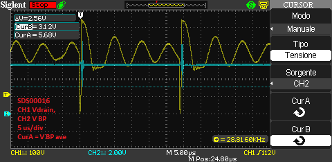
- SDS00016 - CH1 Vdrain, CH2 V BP - 5 us/div
- SDS00017 - CH1 Vdrain, CH2 V BP - 25 us/div
- SDS00018 - CH1 Vdrain, CH2 V FB - 10 us/div
- SDS00019 - CH1 Vdrain, CH2 V FB - 250 ns/div
- SDS00021 - CH1 cat D2, CH2 an. D2 - 2.5 us/div
- SDS00022 - CH1 cath. D2, CH2 an. D2 - 250 ns/div
- SDS00023 - CH1 Vdrain, CH2 cath. D1 - 5 us/div
- SDS00024 - CH1 Vdrain, CH2 cath. D1 - 25 us/div
3. in the pdf file already attached last time there was an extraction from the PI Expert project (it is not possible to attach the project itself due to the file extension), moreover I also attached the actual component layout.
Differences of my real design: D1 VF4007, D2 NTE519, VR1 1N5386BG, BR1 B380D, U2 KB817, T1: Epcos core E 16/5 N27, B66307-G-X127 + coil former vertical B66308-W1108-T1, primary+shields 0.15mm wire, secondary 0.45mm wire.T1 pin change: 1-2 ==> 3,4; 3 ==> 2; 5 ==> 6; 6 ==> 8.
| Attachment | Size |
|---|---|
| SDS00014.png (16.05 KB) | 16.05 KB |
added file PI Expert projectas file gif. If you renamed to uds you get my project.
| Attachment | Size |
|---|---|
| LinkSwitch-XT_PIDesign1 light meter Epcos rename to uds.gif (267.5 KB) | 267.5 KB |
Forgot to say: I replaced the files in the original contribution... apologies for the confusion.
Hi,
It is good to see that the situation gets better than before.
If I understand well, now the issue is the power supply went t auto restart after you increases the load to full load? Correct?
Unfortunately not.
Even at mid load you can see:
- very short tON (600 ns)
- wide ringing starting immediately at tOFF time
- hot LNK363
- low efficiency (<30%)
Could you open the PI9 Expert file I attached last time? Do you think the differences with the real implementation (described in my last comment) are meaningful? May the reason of this behaviour reside in the layout (attached in my first description)?
Thanks for Posting your question into forum and we apologize for the delayed response.
Based on Looking your graphs and waveform , your power supply design is not able to regulate at all.The Switch is not turning at all. The wave forms are not Typical Power supply design waveforms
Let's go Step by step procedure. We are unable to see your PI expert image gif.
(1) Please send us the PI Expert file.
After looking at your schematic, your power supply should start from 195 Vac.
Do the following Steps:
(1) Slowly increase the AC Input Voltage to 195 Vac ,
Monitor the Bulk Capacitor Voltage and don't apply the load.And also monitor the Output Voltage with No Load using oscilloscope and DC meter.
(2) Use differential probe across the Drain to Source Pin , you should see a clean VDS Waveform.
(3) Slowly increase the load until the output falls out.
Could you please do the following above and send us the clear Pictures and data. I Would like to go Step by step procedure and want to do hassle free design.
Also could you please go through the DER135 , it works for your specification and use that as an example.
Thanks,
PI-KSAN
The gif *is* the PI Expert project: since it is not possible to load directly projects in the original format I changed the extension, you should rename it from .gif to .uds.
Anyway, while I was replacing the transformer with a new one (after your considerations I suspected there was something wrong with it) I found that the capacitor C5 was shorted.
After replacing capacitor and transformer everything worked fine.
Thank you for the support.




Hi
I will propose several things to be checked:
1. What is the sampling rate of the scope set up when you measure the voltage.
2. What is the test condition when you record the waveforms, no load, full load? What is the input voltage?
3. Did you make the transformer based on the spec generated by the PI expert? Possible to attached the PI expert design that I can further check for you?