

TOP261 Startup Trouble
I have a design that uses the TOP261 for a 60V, 150W max output. The product this is used in can range from a very light load (about 9W), up to 150W. The input voltage is from a PFC stage at 405VDC.
I'm having some startup trouble when lightly loaded. The drain voltage waveform does not look like the discountinous mode I am familier with and there is an audible noise when this occurs. As I add more load, this problem goes away. I can then reduce the load again and the problem does not come back. Attached are some pictures of both cases.
Any suggestions on areas I should look into? Is this a problem with the feedback components?
Thanks.
Comments
Thanks for the suggestions. I started with taking a closer look at the bias winding voltage. When the power supply starts under light load, the bias voltage has some ripple, with the bottom at 12V and top at 16V. As I add load to the supply, the bias voltage is a constant 16V.
In both cases the output is able to maintain regulation.
I've also looked at the output of the PFC stage. At all times it is a pretty solid 405VDC.
Should I be looking to reduce the feedback resistor?
The bias voltage variation indicates that the power supply is oscillating. You will need to evaluate the feedback loop.
Z. Cochrane


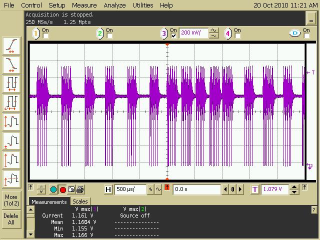

The first thing I would check is the bias winding voltage for the topswitch. If you do not have enough voltage on the bias winding to drive 8 mA into the control pin, the power supply will increase the duty cycle until the bias voltage increases the control pin current. The loop will regain control and will reduce the duty cycle and the control pin current will fall causing the oscillation that I see from your switching waveforms. If this is the case, you will have to increase the bias winding voltage or lower the impedance of the feedback network to allow 8 mA into the control pin.
If this is not the case, then you may have a loop stability issue in the PFC stage, Topswitch stage or an interaction from both stages. I would bias the Topswitch from a HVDC bench supply. See if the problem exists. If so then you need to stabilize your Topswitch loop.
If the Topswitch looks stable, then lightly load the PFC stage and verify its operation. Stabilize if necessary.
Connect the two stages together and verify proper operation. If the problem still exists, then look at the PFC output HVDC to see if it is stable. If it is not, try lowering the Topswitch input impedance by adding a large capacitor at the input to the Topswitch stage (before any filter inductors).
Z. Cochrane