

Topswitch start-up problem.
Hi,
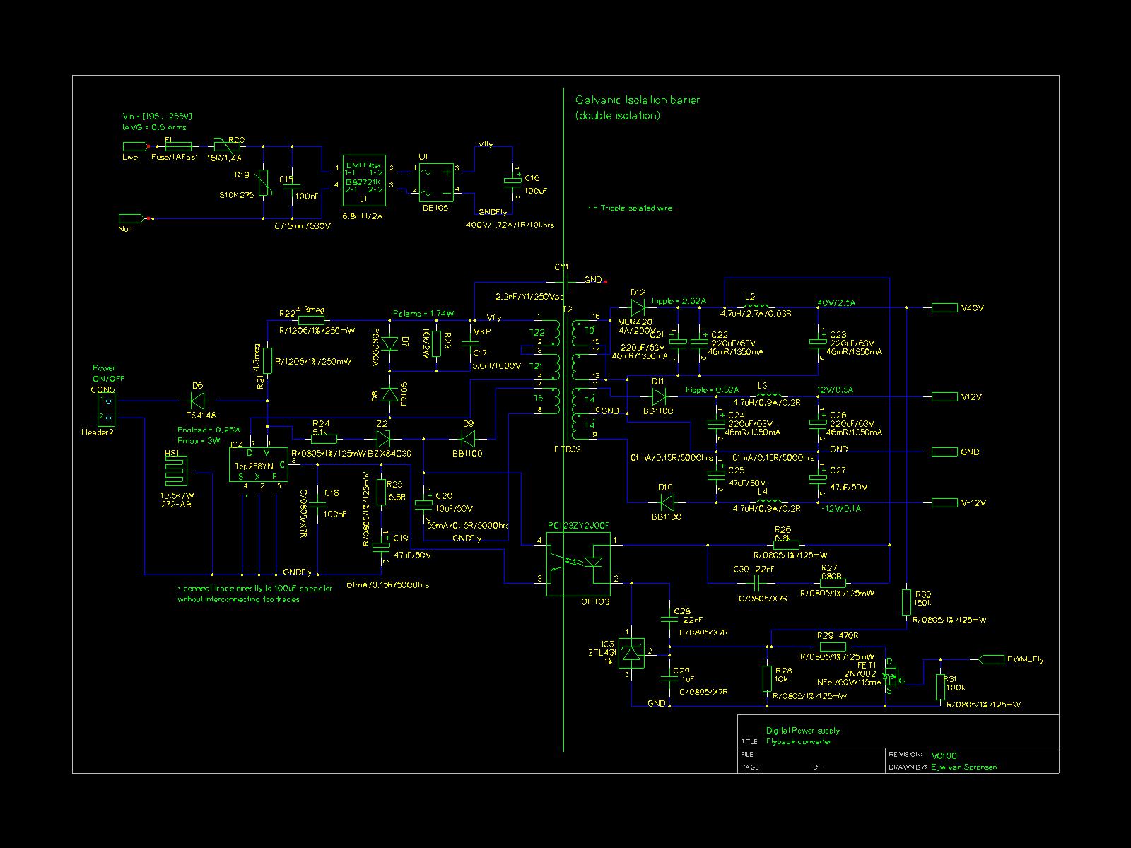
I made the attached schematic. I have a strange problem, that I don't understand. At start-up the Top-switch goes through reset repeatedly. I double checked everything and I really don't understand why it does it. Can someone please help?
Thanks!!
P.S. The 40V output has 13 turn not 9.
Comments
Tanks for you're reply. I have a couple of questions.
- I searched the datasheet but I can't find, that the feedback loop needs to be closed within 64ms. Can you please specify where that is written?
- Is the PWM primary controlled by the primary current or the secondary output voltage?
- I build the flyback converter with you're software as a guide. See attached document. Reduce the output capacitor with a factor of 5 is way off. How much needs the ripple be too let the feedback network work correctly.
I reduced the output capacitors and still no luck. Do you have other suggestions?
- Can you please add a note in you're design software that the max output voltage of the tl-431 is 20V in a sot23 package and for Higher output voltages a additional zener is needed.
The TopSwitch HX has starts as follows: When the power is applied, the control pin capacitor is charged to 5.8 Volts. The switch starts operating. There is a 17 ms soft start period. After that the drain tap (used to charge the control pin capacitor) is turned off. The loop must close before the control pin capacitor discharges 1 Volt (5.8 Volts to 4.8 Volts). The discharge current is called Icd1 in the data sheet. For your device and operating at 132 kHz, Icd1 is between 1.1 and 2.5 mA. A 47 uF capacitor will discharge 1 volt between 19 and 43 ms. Add the 17 ms for the soft start time, you have between 36 and 60 ms for the loop to close before auto-restart occurs. I was wrong when I stated 64 ms (that is for a TinySwitch device).
The PWM control is by secondary output voltage feedback to the control pin.
The suggestion to reduce the output capacitance was for a quick test to see if the power supply was not closing the loop within the auto-restart time due to excessive output capacitance. A better way is to measure the main output voltage and the control pin voltage with a scope. If the output voltage reaches the regulation voltage before the control pin decreases to 4.8 Volts, then the output capacitance is acceptable. If this is the case, then you will need to see if the feedback loop is providing 2.5 mA or more(Ib in the data sheet) to the control pin. When troubleshooting a new power supply, it is sometimes easier to temporarily remove the TL431 and bias the opto with a zener diode. This reduces the complexity of the feedback circuit and helps isolate where the problem.
Z. Cochrane
Hi,
I can't find the problem. Hope you can help some more. I don't think the problem is in the feedback loop. I think there isn't enough energy transferred within the 30 - 60 ms. To start up properly.
The top258 switches at 34 khz?? See attached pictures. How is it possible the switching frequency is lowered? What also troubles me is the noise on pin V. See attached picture. Is this normal? The last picture is the output voltage at the 12V output without capacitors but with diode and 10k load.
Thanks,
Ernst
The switching frequency is variable when the control pin current is above Ico2 (see figure 9 in the data sheet). This information indicates that you are getting feedback current to keep from going into auto-restart (control pin current greater than Icd1 in figure 9). If the output is not getting to the expected voltage before the device turns off, you may be getting too much current into the control pin. If you are using a TL431 for the feedback reference, try replacing it with a zener diode (approximate output voltage = zener + Vopto diode. This is a temporary change to isolate the cause of the problem. If the power supply starts, then you need to troubleshoot the TL431 circuit to determine why it is not regulating correctly.
I do not know why the V pin is being pulled down. If the power supply doesn't start with the zener feedback, then short the V pin to the source pin. This will disable the V pin function. If the power supply starts, this isolates the V pin as the problem.
Z. Cochrane
Thanks for the reply.
I shorted the V pin no luck. Is there a way to provide the feedback with the bias winding?
So I can test if the topswitch will start-up?
Ernst
You can regulate the bias winding. However you may want to consider shorting the primary and secondary grounds and make a direct feedback connection using a resistor divider and an emitter follower to the control pin. Also you can use a bench power supply to support the bias winding. Connect the bench supply through a diode to the bias supply's rectifier (cathode to cathode). This will diode OR the two supplies.
Z. Cochrane
Hi,
I have tried an emitter follower to get the top258 starting. No luck. I reduced the bias winding capacitor to 1uF. and placed a 100k resistor divider over that capacitor and connected a bc857 with its base on the divider and the e,c on the legs on the opto output pins.
The result:
A continues switching top258 at 4khz and a no load output of 10V (in stead of 40V) when I connect a load. The output is 0V and the switching frequency doesn't change.
I really don't understand why the top258 isn't starting properly and why there isn't and power transferred. I'm a bit out of options.
Hope you can help. Thanks.
Ernst
Make sure that the opto transistor is disconnected from the circuit when you test the transistor circuit. Please send me a photo of the drain voltage and the 40 Volt output as the power supply tries to start. I want to see the time the drain is switching vs the output voltage. This will show me where the amplitude of the 40 V output when the Topswitch stop switching.
Z. Cochrane

The feedback circuit must supply at least 2.5 mA into the control pin in under 64 ms for the power supply to successfully start. I would reduce the output capacitance on the 40 Volt and 12 Volt outputs by a factor of 5. Verify that the output voltage gets to the desired level in less than 64 ms. If it does and the power supply still does not start, check the feedback path to make sure that it can deliver between 2 and 8 mA to the control pin.
Z. Cochrane