
LNK625 power output burps
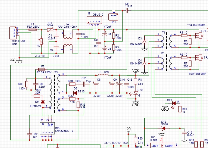
Our product, a controlled intermittent half bridge inverter, uses LNK625DG-TL as an auxiliary power supply. The switching power supply uses the main circuit 310VDC for power supply, and the power output unit 17VDC supplies power to the control circuit and drive circuit. The switching power supply uses a typical application circuit of LNK625. Attached is a screenshot of the circuit diagram.
About half of our products have power problems. When the inverter (whose load is a high-frequency transformer) operates without load, the power output and inverter circuit are always normal. When the secondary load of the high-frequency transformer is loaded, the output of the power supply will stop in half of the cases (not every time there is a problem) when the load is already working, and then the output will resume immediately.
I think this may be because the power circuit has entered a protected state. It can be said that whether the inverter is loaded or not, the power supply current of the power supply is the same, because the power consumption of the control circuit and the drive circuit is the same. In both cases, the actual measured power output current is 0.1A@17V. When the inverter is loaded, the voltage of the main 310VDC only slightly drops.
The power supply uses a "PIExpert design" design. See the attachment for design documents.
Excuse me, what causes the power supply to hiccup? How should I find the cause?
Looking forward to reading from you.
Best Regards
JJ
Files
| Attachment | Size |
|---|---|
| Link62x-DIP-EE19_Copy00.uds | 611 KB |
| 625_0.jpg | 128.7 KB |
Comments
Dear Wrench,
What you mean is that it is possible that the saturation of the drive transformer may cause overcurrent protection in the power supply.
The phenomenon on my side is that the load of the half bridge circuit is a high-frequency switching transformer. When the transformer is not connected to the load, the driver works, and the power supply never enters a restart state. Only when the transformer is loaded can the power supply sometimes enter a restart state. The driving circuit of the half bridge circuit is operational in both no-load and load states of the transformer. Will the load cause saturation of the transformer in the drive circuit?
Of course, I can immediately test the possibility you mentioned. Please provide a detailed suggestion on where to add what components.
Best wish,
JJ
I don't know how exactly you are constructing the drive transformer, but if the reset winding has the same number of turns as the drive winding, it will require the same amount of volt-seconds to reset the transformer as was originally impressed across the drive winding during the on-time of the TL494 driving the transformer. I am assuming (correct me if I'm wrong) that you are running close to 50% duty cycle, with some dead time to prevent shoot-through.
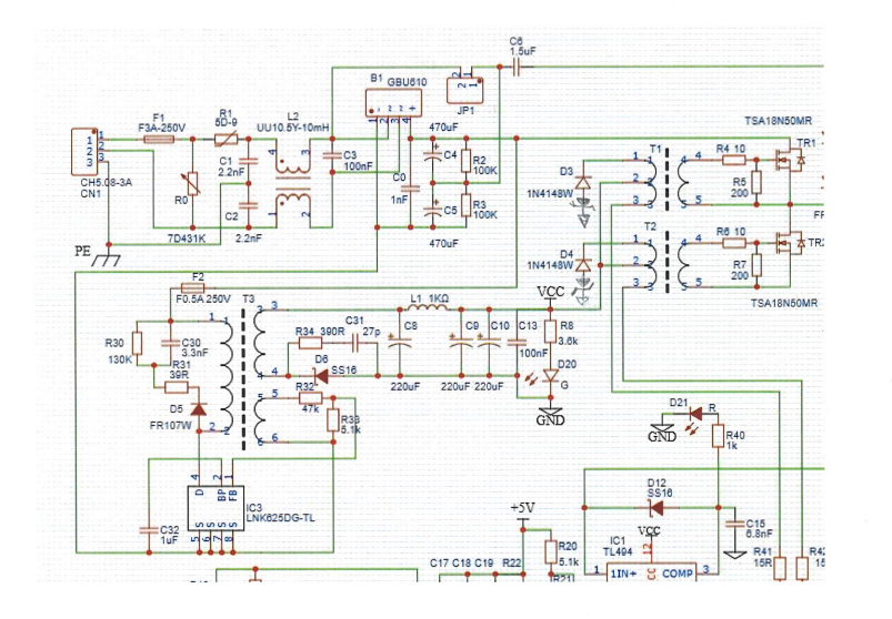
I have attached a scan of the schematic with added zener diodes for better reset, The zener diodes should be equal to the output voltage of the LinkSwitch flyback supplying the transformer (with maybe a little extra). This is assuming that the reset winding has the same number of turns as the drive winding. You can probably accomplish the same thing using a resistor in series with the diode, but you would need a good grasp on the amount of magnetizing current built up in the drive transformer primary during on-time to properly calculate the volt-seconds area (and hence the resistor value) needed to completely reset the transformer.
| Attachment | Size |
|---|---|
| zener_reset.png | 601.95 KB |
This is somewhat of a guess on my part, but I'm concerned that the transformers used to drive the fets in your schematic have only a single diode drop to reset them. If either drive transformer saturates, this may cause the Linkswitch to go into OCP. I would suggest adding a zener diode or resistor in series with the diode to add extra reset voltage.