
InnoSwitch3-CP on output voltage 24V and current 2A
Good day to all. Not long ago, I started designing InnoSwitch3-CP based UPS on an output voltage of 24V and a current of 2A. Of course, if you open the DataSheet to this chip, then the manufacturer does not mention any 24V, but it’s about 5V, 6V, 9V, 12V, 15V. But without hesitation, calculating the feedback divider at 24V, picking up the necessary 220/24 transformer and calculating the necessary nodes in the circuit a bit, I proceeded to wiring the printed circuit board. In practice, when the circuit board was already at hand and nothing stopped me from starting my UPS, I ran into a problem. Namely, as it turned out, the projected UPS functioned in the twentieth century, but the picture changed dramatically when the minimum load was connected. In the process of experiments, even with a load of 224 ohms, my UPS did not start. After that, I began to study in more detail all types of protection of the InnoSwitch3-CP chip used by me, as well as having armed myself with a multimeter and an oscilloscope, I began to analyze the operation of my UPS. As a result of all the research, I came to the conclusion that the protection works in the secondary circuit and it is connected with the "Output Constant Current and Constant Power Regulation", or with the "Output Overload Protection", but either because of the "clumsy" level of English, or from Because of problems with logic, I can’t figure out how to get around these problems. Maybe someone who has a lot more experience than me in designing the UPS can suggest a solution to the problem, and maybe someone worked with this chip and also encountered similar difficulties. Do not judge strictly, I attach a link to the topic: oscillograms, the circuit of my UPS, the DataSheet of the transformer as well as the DataSheet of the microcircuit. I would also like to immediately clarify about the output. In the passport of the microcircuit, a threshold voltage of VOUT 27V is indicated, then why PI EXPERT recommends installing a zener diode on this output?
Files
| Attachment | 大小 |
|---|---|
| Proekt.zip | 4.25 MB |
回應
Here is an example of a design report which goes above VOUT threshold of 27V. https://ac-dc.power.com/design-support/reference-designs/design-examples/der-666-45-w-power-supply-using-innoswitch3-ce/
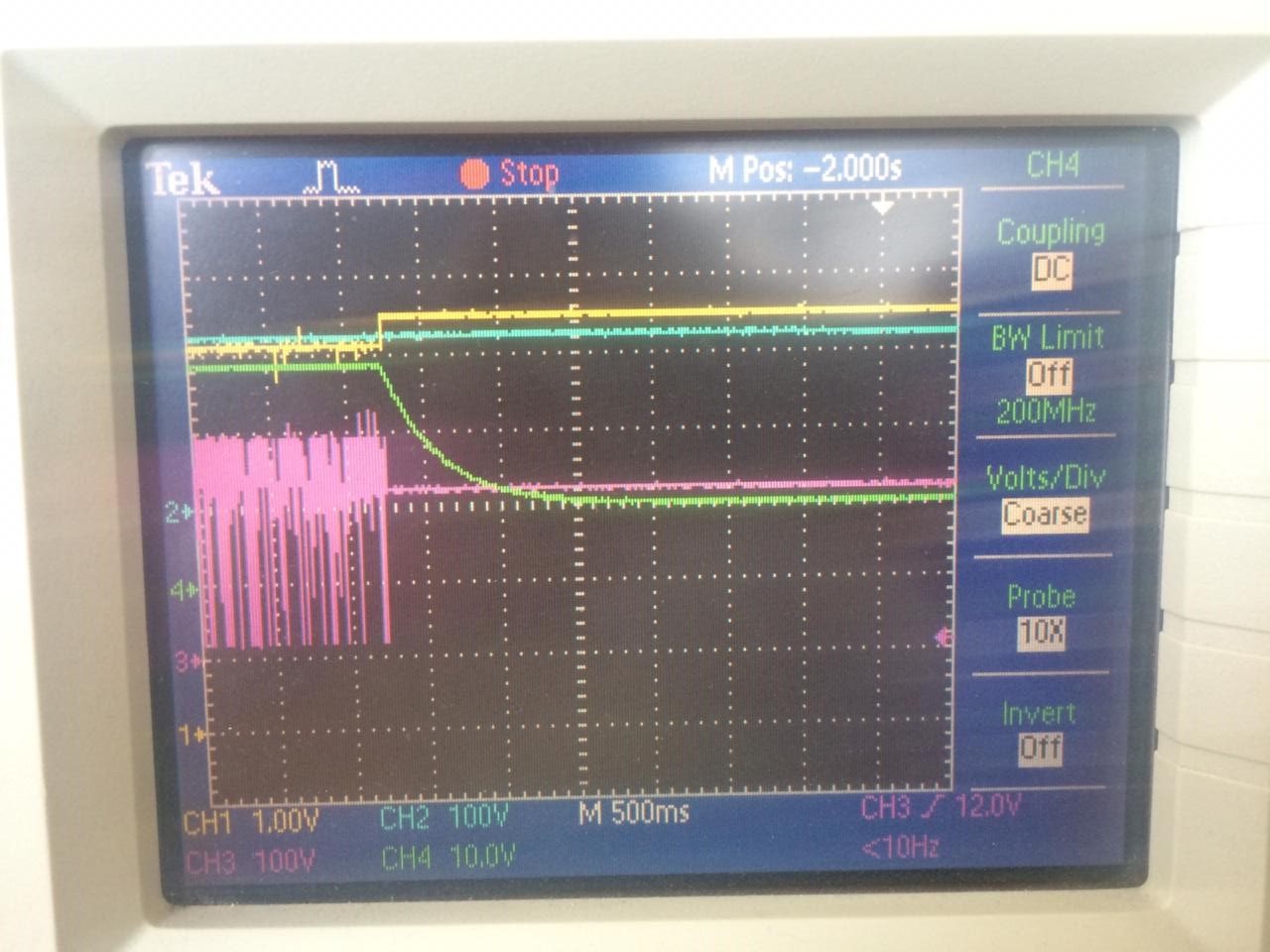
Not quite understand the first question. Regarding the minimum load, when I loaded my UPS with 56 ohms, I only saw this picture on an oscilloscope applying a photo (blue graph-rectified voltage after a diode bridge, yellow graph-voltage on the BPP contact, purple graph-voltage on the drain of the transistor,green graph-voltage on the bias winding ). The chip, when I realized, enters the automatic restart mode, after the voltage rises to 100 V, while at the voltage the voltage rises to 24 V, which can be perceived at the oscillogram. Is it an overvoltage on the BPP contact?
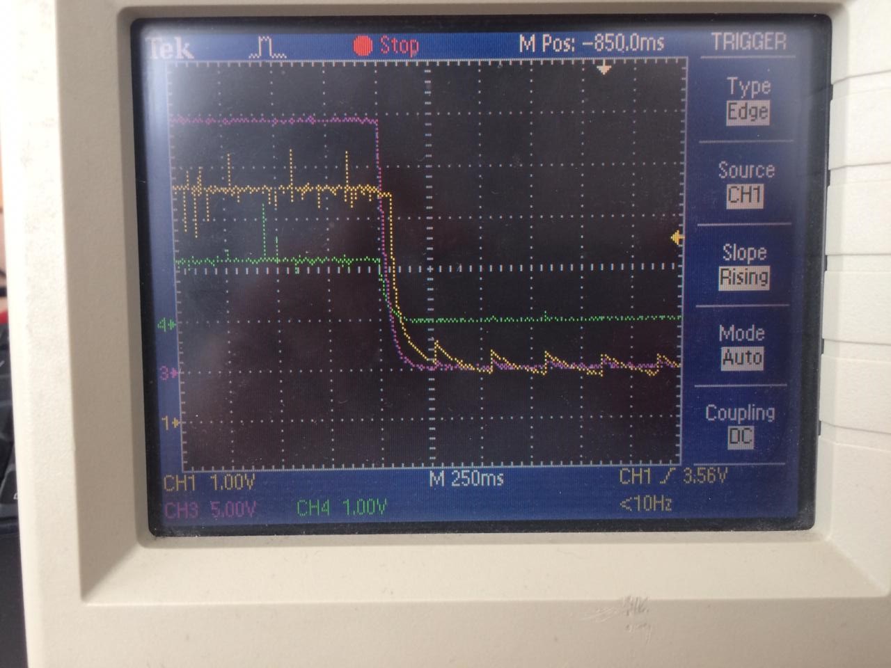
As for the secondary side, the following happens there, I attach a graph from an oscilloscope (yellow graph-VOUT, purple-FB). The tripping moment occurs when the voltage on the FB contact reaches 1.22 V, and the output voltage rises to 24 V, and this with the same rectified input voltage. The graph shows off time. I have a 24V output, I think the zener diode in my case is not needed to protect the VOUT contact.Sorry for my English.
Hi Ensider,
Could you plot the waveform at 5seconds/div?
I observed on the waveforms, that the auto-restart OFF time is about 2seconds so it the fault is on the primary side.
It could be that the primary OVP circuit triggers or the Line OV protection. Try increasing the V-pin resistors (R44 & R47) to 4M-ohm or trim the resistance (R40) of the primary OVP circuit.
Regards,
PI-Pike
Hello,
PI-PIke
Did not quite understand what fragment you are interested in.Today I lowered the resistance of R40 to 100 ohms, I applied the oscillogram of disconnecting the microcircuit, the voltage was applied from a laboratory power source DC (blue graph-rectified voltage after a diode bridge, yellow graph-voltage on the BPP contact, purple graph-voltage on the drain of the transistor,green graph-voltage on the bias winding ).Increasing the resistance on the V-pin contact to 4 MΩ caused the microcircuit to stop turning on altogether. What could be the reason for turning it off at 220 V, DC at the input? Perhaps more oscillograms are needed to better identify the system malfunction? Thank.
Hello. In the process of research, our UPS still started up at the maximum input voltage. The problem was in the FET installed on the secondary side of the UPS, it had to be abandoned for a while and an ultra-fast MUR 1560G diode was installed. At the moment, the maximum power that it gives out 15 W. What could be the reason for such a voltage drop at the output? Maybe it's in the modification of the chip, we bought INN3268C-H202-TL? Thank.
Hi Ensider,
What is the output voltage when it is in 15W power?
Try reducing the IS current limit resistor. Reduce it to 10mohm (0.01). It could be that it hits the current limit or constant power when you are loading the UPS.
Regards,
PI-Pike
Good day, dear PI-PIke!
It's been a long time since my problem arose. To date, my problem has been resolved, my UPS is operating at full capacity, which the microcircuit is capable of delivering. But one question remained about the filter, which is shown in the attachment file. How is it calculated? Thanks!
| Attachment | 大小 |
|---|---|
| Snimok.PNG | 48.2 KB |
Hi Ensider,
We dont have calculation for the feed-forward circuit. This circuit helps on reducing the output voltage ripple. The default is 1nF capacitor and 1kohm resistor, and could be increased to meet the output voltage ripple spec.
Regards,
PI-Pike
Good day, dear PI-PIke!
I was looking for information about the parallel operation of power supplies, but I could not find anything. The task arose to increase the power of the current power source by connecting the same one in parallel to the first one. Please tell me, does the InnoSwitch3-CP allow such a modification? Considering the current limiting function.
I also wanted to ask about the current limiting line. Why, when I put a resistor with a nominal value of 0.003 Ohm, the 24V channel gives out a maximum current of 2.5A, and when I put the calculated value under this current of 0.01, the microcircuit begins to choke by 1A. What could be the reason for such a malfunction? Now there is an INN3268C-H202-TL microcircuit. Thank you!
Hi Ensider,
Here is a DER application using two Inno3-CP devices. https://www.power.com/design-support/design-examples/der-551-54-w-dual-usb-pd-charger-using-innoswitch3-cp-and-cypress-ccga-controller
Regards,
PI-Pike
Hi Ensider,
Could you please send me your current limit circuit for better understanding. Thank you!
Regards,
PI-Pike
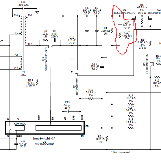
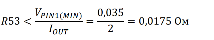
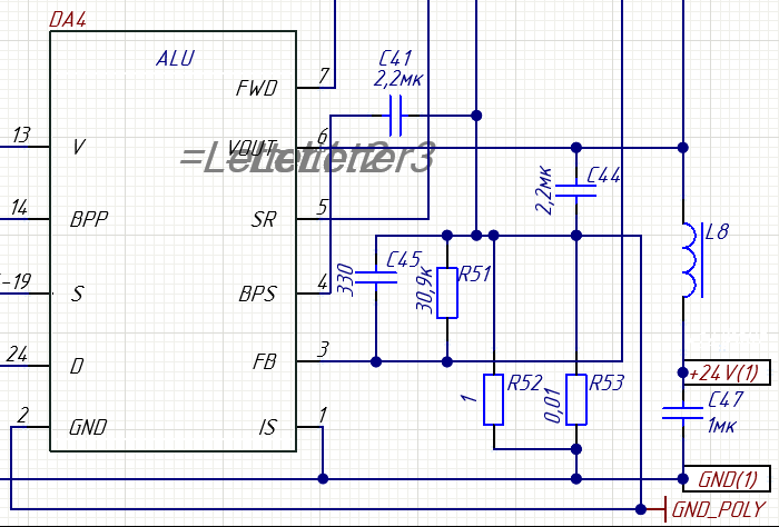
This is my current limiting line. Circled in red. Current limitation calculations.
| Attachment | 大小 |
|---|---|
| Снимок.PNG | 67.86 KB |
| Снимок_0.PNG | 17.04 KB |
Hi Ensider,
Could you try connecting your current sense resistor to ground of C47? That's where the load current will flow.
Regards,
PI-Pike
Hi PI-PIke!
After this connection, I will simply exclude the current limiting node.
| Attachment | 大小 |
|---|---|
| Снимок_1.PNG | 53.14 KB |
| Снимок_2.PNG | 51.01 KB |
Hi Ensider,
Could you please put a legend/description on each waveform you uploaded? In which cases you get these waveforms? Thank you!
Could you please also describe what fault happens when you put minimum load in your UPS? Does it auto-restart immediately? If yes, how long is the OFF time?
You need a zener diode to protect the VOUT pin if your Output Voltage is greater than the VOUT threshold voltage of 27V.
Regards,
PI-Pike