
Adding more leds to an existing LNK-306 design
Hello,
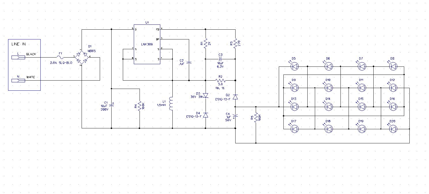
For years, we have been producing a product that runs a string of 8-leds in two parallel strings of 4 in series at about 350mA total current. The circuit implements the LNK306 chip in a non-isolated format, as explained in AN-37. Our customer has recently Decided they want to double the amount of leds in the circuit. I figured keeping the output current the same, and doubling the output voltage would be the simplest means to achieve this.I have attached the updated schematic, as I thought it would work. I have only changed the size of the protective zener diode to 36V from 18V, and the voltage ratings of the Cfb capacitor to allow for a higher output voltage. I have retained the values of the Rsense resistor, and the bias network recommended. However, the circuit now goes into the classic .8sec reset condition. What should I be looking to change to correct this? I think I read I should be getting 1.65v at the FB pin, in reference to the Source pin. How long should this stay at 1.65v? Also, how can I possibly measure for the 49uA current limit? I tried to increase the Csense capacitor from 10uF @6.3v to a 22uF, no difference. I have also tried to increase the value of Cout from 1uF to 10uF, without any change. My sense resistor is 5.6-ohms, 1/2W. Any further info would be greatly appreciated, as always.
Comments
Thanks for the info. I thought I attached the schematic, but I think I had it in pdf format.So maybe it didn't take it. I was hoping the inductor would stay the same, since it was the same current. I was hoping for only a change to the divider network on the fb pin being an issue. I tried to use the PIexpert download version, but didn't see any provision for this type of circuit.
| Attachment | Size |
|---|---|
| Reference design | 102.13 KB |
Hi Richard,
Thanks for sharing your schematic. There is a need to increase the inductance to be able to deliver higher output power. Your topology is buck-boost design which is available in PI expert. Could you also give me the Input and output Voltage range requirement? Thanks
Hello,
My input range is Universal power, so I figure 100-277, my output range is CC 350mA, if possible, with 21.6V - 23.2V range. I was looking for CC topology, but I only selected buck for some reason. Any help would still be appreciated. Thanks. The actual device we are using is the LNK306GN-TL. Is there a device we could increase the operating frequency so that I don't need as large of an inductor?
Hi Richard,
I have attached the PI expert design and the suggested modifications in the schematic for you to verify. Hope to hear from you soon with the results.
| Attachment | Size |
|---|---|
| PI Expert Design for Buck Boost | 460.33 KB |
| Suggested Modification based from PI Expert | 271.73 KB |
Hi! Thanks for the info! I too did that finally this morning using the buck//boost topology, instead of the buck. I'm glad to see we came up with the same results. The only thing I wasn't too sure of is changing the 270-ohm to a 24.68-ohm resistance. I was going by the AN-37 value they show which was 2k and 300 ohm. For some reason I was thinking these were fixed values using the CC LED circuit. I still don't fully understand what's happening with that fb input after reading it several times, other than it is looking for a 1.65V at 49uA input, and that if it isn't good, it goes into the .8s reset cycle. I'm almost afraid to try to measure anything in fear of using the wrong reference point!! I do have an isolation transformer though,at least. I'll let you know how it goes. Thanks again.
Hi Richard
Hope You are doing fine. Circuit location R3 should be 24.68 Kilo Ohms not Ohms. R3 will set the output voltage to 23.2V.
Hello,
I did all the changes as recommended, and I'm still getting a .8s flasher. In the reference LED design in AN-37 it shows a 2k and 300-ohm for the Rfb and Rbias. It seems like 24k is a big difference in value. Any more clues? I didn't get any warning or anything when I put the values in the PI-Expert calculator, including my inductor resistance, etc. Any help would be appreciated asap! Thanks.
Hi Richard,
Yes you are right it should be close to 300 Ohms. Sorry for the confusion. Can you try increasing R2, say 10 Ohms to verify if the auto-restart is due to overload. Also , have your tried increasing the input capacitor 33uF?
Hello PI-Martok,
I switched back to the 300-ohm. I switched the 5.6-ohm sense resistor to a resistor sub box. The circuit will work okay with a 7-ohm resistor down to 88VAC input, but to get it to work at 6-ohms, I have to increase the input voltage to at least 100VAC. So maybe this clue will help. All I know is I have an anxious customer. Should I have an output cap on this circuit? I also for some reason have a pre-load resistor of 5.1k. This circuit also switches between the flood array shown, and a single-led spot lamp, and I think it was put in to keep the spot from a single flash before it turned on. I have a 100k shown on the schematic, but I believe this is why it was reduced to the 5.1k.
Is there a safe means that I can probe the FB input, to capture what we are seeing? I could use a scope with 2 inputs as a differential input, but what would I reference the pin to? The Source pin?
Just wondering what else I could be looking for to stop this. Thanks again. Please see previous comment.
Hi Richard,
C4 is the output capacitor and it was too small. Please also try to increase to 220uF/50V to reduced the voltage and current ripple. Could be one reason why the device is doing auto-restart since the output is sense for the regulation.
The pre-load resistor R5 prevents the output voltage to go up during no load condition lowering it down will affect your standby power. The recommended value is 30mW resistor power dissipation (R = 24^2/0.03 = 19.2Kohms).
You can try to probe the FB pin to source.
Regards
Mark
Thanks again for the advice. Much appreciated. Unfortunately, I cannot access our lab at work due to mandatory shut downs. I will definitely try it out!
Hi,
220uF? That seems high to me. The AN37 says the following:
The output capacitor is optional; however with no output capacitor the load will see the full peak current (ILIMIT) of the selected LinkSwitch-TN. Increase the value of CO (typically in the range of 100 nF to 10 uF) to reduce the peak current to an acceptable level for the load. So is it acceptable to put in that large of a value?
Also, I did some measuring around the FB circuitry, using a Fluke DVM. The value I get across the Rsense is 1.7V.
The voltage I get at the FB pin in reference to the Source pin, is 1.56V. Does this seem right to you? I thought the chip was looking for 1.65V at the fb to keep running. This is with a 6.8-ohm Rsense resistor. Thanks.
Hi Richard
Since you have doubled the output power, Please increase the the output capacitor a little bit maybe around 22uF and see if the output will get any better.
The FB pin voltage depends on your output load. If you're output load is less than 350mA then you FB pin is <1.65V.
Can your also send me your board picture that shows the layout? thanks.
What is all this garbage? Do I need to change my password? My current output cap was 1uF, I increased it to 10uF, no difference. It doesn't flash right away, it takes about a minute before it starts it, and then it isn't consistent. I don't know if this will help. None of the parts seem to be getting too hot, at least not to the touch. Could one of my components be breaking down as it warms up? By the way it will run continuously with 2 strings of 7 leds, but when I increase it to 8 is where the problem starts. I'm lost at the moment. I will send the layout if I have a link to contact you directly or put it here without all to see.
Hi Richard,
Good day!
Apology for the spams. The page is public and we are trying our best to maintain it in such a way that only the important information will be displayed. I have already removed all those spams in the page. In the meanwhile, PI-Martok will continue to help you out in your concern. Please bear with us.
Thank you and Regards,
PI-Lupin the Third
Hi Richard
I think the overload protection is kicking in with 8V LED string. The system were not able to deliver the required full output power even when switching without cycle skipping. This result to auto-restart operation. Have you tried increasing Inductor L1 maybe around 2.7-3mH? Please also increase the input capacitor if the problem happens at 85VAC.
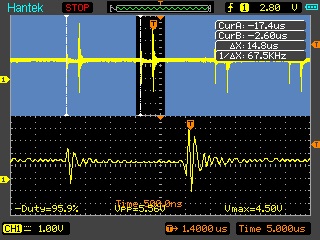
After finally getting the means to look at the fb pin, I can see there is a ringing occurring with a pk to pk value of 6v, of which 2v is below the source reference level. I will attach a scope capture tomorrow. I'm not sure if the ringing is due to saturation, or the switching diode.
After finally getting the means to look at the fb pin, I can see there is a ringing occurring with a pk to pk value of 6v, of which 2v is below the source reference level. I will attach a scope capture tomorrow. I'm not sure if the ringing is due to saturation, or the switching diode.
By the way, the led string voltage is around 23 volts. Two strings of 8 in parallel.
I have attached a sample of the FB pin, which shows the ringing on the pin, which corresponds to the leading and trailing edge of a switching pulse.
| Attachment | Size |
|---|---|
| FB_Pin.jpg | 42.67 KB |
Here's a partial board layout. You will not the inductor in mounted on the bottom of the PCB and tie wrapped into place for mechanical reasons.
| Attachment | Size |
|---|---|
| LNK306 layout on our project | 164.04 KB |
Hi Richard,
Thanks for the inputs. The noise your have seen in the FB pin voltage probably came from the ripple voltage across C3 or From noise coupled from the MOSFET internal to the IC. You can increase C3 to minimized the ripple . Also if the noise came from noise coupling generated from the MOSFET switching, you can try minimized the loop from C1 to Drain by adding 10nf/500V across D-S pin.
I also observed the you added a 100K bleeder resistor (R4) across the input capacitor. Can you also try to removed it and see the difference? R4 has a high power dissipation (0.16W at 90V and 1.5W at 277VAC) might me causing the power delivery issue.
The layout looks good except the drain trace loop is big. The positive terminal of the Output cap C1 must be as close as possible to D pin (5).
Can You also capture the VDS Switching waveform or Drain current waveform before the device has gone to auto-restart? We can verify from the waveform what is causing the Auto-restart .
Thanks for the information! That gives me quite a bit to try out, and I'll get you the VDS waveform.
My 100k is probably too small, physically, now that you mention that. I also noted s 26v pk to pk ripple on the DC input, that seems like alot. One question I did want to ask, is it better to have less leds in series and more in parallel, than the other way around? I was thinking less current would be better. But I may be wrong. Would a small value cap across C3 help, in addition to the 10uf? thanks. I'm using my portable scope without power connected to get the readings.
| Attachment | Size |
|---|---|
| Voltage waveform Vds, referenced to D pin. | 42.52 KB |
Hello PI-Martok,
Did you mean 10pf or 10nf, that would be .01uF, correct? I tried a .01uF first, and it flashed at a dim level right away. Then I tried a .001uF, still flashed, but at normal brightness, and still right away. The ringing on the fb pin was absent I could see. So maybe an even lower value?
Hi again, I removed the100k on the input cap. it didn't seem to have any affect on it. Please also see previous two comments. Thanks.
Hi Richard Wright,
Good day!
I am not sure if you are also receiving spams these past few days but I've been receiving a lot for this post. I had to clean the page every time so it won't appear again. With that, I will close this post for now and I would suggest that you create a new post for this same inquiry. I will still delegate this to PI-Martok since he has responding you from the start.
Thank you for your understanding and I am looking forward to your new post.
Best Regards,
PI-Lupin the Third
Hi Richard,
Good day and Thanks for using Power Integrations LinkSwitch TN. Since you doubled the output power, It could be that the 800ms reset is due to output overload. I didn't see your attached schematic on your post, but if you haven't used the PI expert online then it would be helpful for You to use it on your new design. The PI expert will give you an idea what needs to change if you update some parameters on your current design. I tried to used to check what happen if your double the Vout assuming you used Buck-Boost topology. It says in the PI expert that You need to increased the input capacitor and Inductance value. Here is the PI expert online link. You need to create your account so you can use it . When you enter the site, Create New Design and pull the drop down menu to locate the LinkSwitch-TN and select your topology. Please also attached your schematic again and your input and output specification so I can review and recommend solutions.
https://piexpertonline.power.com/site/index