
Power Supply Design Using INN3949CQ
Hi Power Integration Team,
We want to develop a 48V, 0.5A isolated power supply using the INN3949CQ.
Input voltage is Universal AC.
Is it possible to develop up to 48V supply using IC INN3949CQ?
Thanks & Regards
Pemendra Pardhi
评论
Hi PI Waer,
Thanks for the reply and suggesting the solution.
Thanks & Regard
Pemendra Pardhi
Hi PI Waer,
I have one query.
I want to provide under-voltage protection.
If the input voltage goes below 90Vdc, then the power supply must be turned it off.
For enabling the under-voltage protection, Figure 15 is provided in the data sheet (https://www.power.com/sites/default/files/documents/innoswitch3-aq_family_datasheet.pdf)
But i am unable to find out the value of suitable resistance, any designed reference manual i shere for the same.
if available, please provide the reference.
Thanks & Regards
Pemendra Pardhi
Hello Pemendra,
On page 21 and 22 of the datasheet, you can find the UV/OV brown-in/brown-out threshold and UV/OV overvoltage line threshold. As long as the currents entering the V pin falls within these limits, then the InnoSwitch will operate normally but if it is outside this range, then it will trigger the protection.
In your case, as long as the current entering the V pin below 90Vdc is below the UV/OV brown-in/brown-out threshold then the device will stay in UV protection mode.
Hi PI- Waer,
Thanks for the reply,
I have just required another one's help,
If it is possible to review the schematics and design components?
If it is possible, then please comment on the attached drawing schematics, their BOM and Magnetics Design.
Thanks and regards,
Pemendra Kumar Pardhi
| Attachment | 大小 |
|---|---|
| Battery Charging Circuit.zip (432.16 KB) | 432.16 KB |
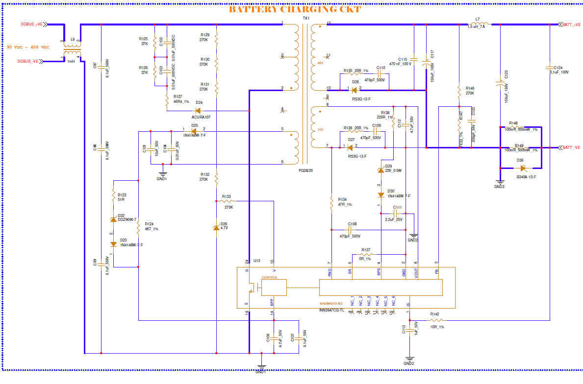
Hi Team,
We have designed the battery charging circuit.
The schematics are attached here.
Our objective is to achieve the output voltage of 48V for battery charging.
But the given circuit is not working above the 12V.
As per the specification of the IC, it will work up to 24V. However it is woking above to 12V
What will be the reason?
Thanks
Pemendra Pardhi
| Attachment | 大小 |
|---|---|
| Battery Charging Circuit_1.png (110.07 KB) | 110.07 KB |
Hello Pemendra,
It is possible but you will need to make two windings for the output. The reason for this is because the Vout pin of the InnoSwitch3-AQ has a maximum rating of 27V, so you will need one winding for your 48V output and another winding sized below 27V for the Vout pin of the InnoSwitch3. You can see an example of this implementation in our LytSwitch-6 LED drivers where they have higher voltage requirements. I will link one of the LytSwitch-6 DERs for reference.
DER-901: DER-901 - 125 W 2-Stage Boost and Isolated Flyback 3-Way Dimmable LED Ballast Using HiperPFS-4 and PowiGaN-Based LYTSwitch-6 | Power Integrations