
INN3164C-H10 - Switching frequency modulation
Hi there!
I'm currently designing an AC/DC Flyback using the INN3164C-H10. I followed the design guidelines provided in AN72 and read the other related topics in this forum. However, I still don't understand how the controller is modulating the switching frequency. The main specifications I'm testing during this bring-up phase are as follows:
- 150VDC input.
- 5V/2A max. output.
- 80kHz desired switching frequency at full load.
- Lm = 560uH.
- Npri / Nsec = 10 (Npri = 60; Nsec = 6).
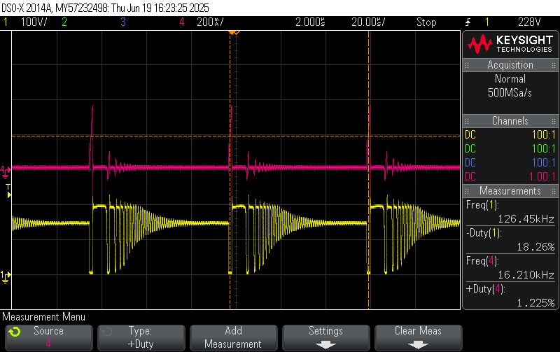
I have designed my Flyback transformer to always be operating in DCM (CrCM inductance at 110VDC = 670uH, which will be my minimum input voltage). At no-load, the switching frequency starts at 17kHz at no load and rises to only 33kHz at 0.8A (images attached: internal MOSFET's Vds and current through the primary winding) . This is not what I want, because at this operating point the transformer is almost saturating because the switching frequency is not increasing as much as I would like. This transformer is designed quite far from saturation (263mT peak flux density at 80kHz), for an RM5/I-3C94 core. However, if the switching frequency doesn't increase (I tested at 1A and it only rose to 37kHz) the transformer will saturate and also the primary overcurrent limit will be reached (~950mA typ. with C_BPP = 4.7uF). Could anyone explain to me why is the switching frequency not increasing or how exactly is supposed to increased? I thought at the beginning that it would linearly increase from 0% to 100% of the load based on the voltage measured across the shunt resistor in secondary side (from GND to IS pins), but it seems not to be like that. Furthermore, based on the datasheet, the switching frequency during the start-up should range from 23-27kHz, and I'm getting ~16-17kHz. Could it be because I'm using CBPS = 4.7uF instead of 2.2uF? I'll test that right away, but could anyone help me understand it in the meantime? :)
Thanks a lot for your time and I'm looking forward to your replies!
Best regards,
Juan Antonio Serrano
评论
Hello Juan,
Thank you for reaching out. Based on the waveforms you sent, the transformer does not seem to be in danger of saturating.
The 950mA current limit is not primary overcurrent protection but the peak primary current that the controller will target during normal operation. so as long as the current is still within 864 - 1036mA (Limits in the datasheet) then the design is unlikely to be near saturation point. In your waveforms, you can see that at no load the current limit is lower because the device lowers the current limit so that it can operate at a high enough switching frequency to reduce audible noise. You can find details of this on page 4 of the datasheet. So, the reason why the frequency change of the from no load to 0.8A is relatively low is because the device tries to maintain a high enough switching frequency to reduce audible noise. You should typically only reach your target switching frequency (80kHz) at around full load and minimum input voltage.
The IS pin on the secondary side is not used for switching frequency but for output overload protection. So it will only trigger when the output current being drawn exceeds the target over current limit set by the IS pin resistor.
Hello,
All clear now! I thought the "ILIM" current limit was the maximum allowed current through primary, not the peak magnetizing current target for the current control loop, which based on this I assume is PCMC. I just changed the CBPP capacitor to 470nF to decrease the magnetizing current peak target and it's working fine now.
Thanks a lot for the quick answer and have a nice day!
Best regards,
Juan
Updates:
- I tried lowering down CBPS to 2.2uF as used in the datasheet --> No change.
- I also winded another transformer, building it a bit further away from saturation but with the same magnetizing inductance (Npri / Nsec = 10 (Npri = 70; Nsec = 7). I confirmed that the transformer is not saturating, but the overcurrent limit (~875-900mA) is reached in primary instead when the 5V output is demanding 1A. These values correspond to the calculated magnetizing peak current in DCM based on the switching frequency at that moment (~35kHz). I don't really understand why the controller is not increasing the switching frequency, to be honest. Even though it might be a complex algorithm, could anyone provide an expression about how the switching frequency is related to any parameters of the converter? It's written in many places that it depends on the load, the magnetizing inductance, etc., but I cannot understand why more details are not given in this regard.
Thank you again for reading and all ideas are really appreciated!
Best regards,
Juan Antonio Serrano