
INN3672 keeps restarting at very low load
Hello Community,
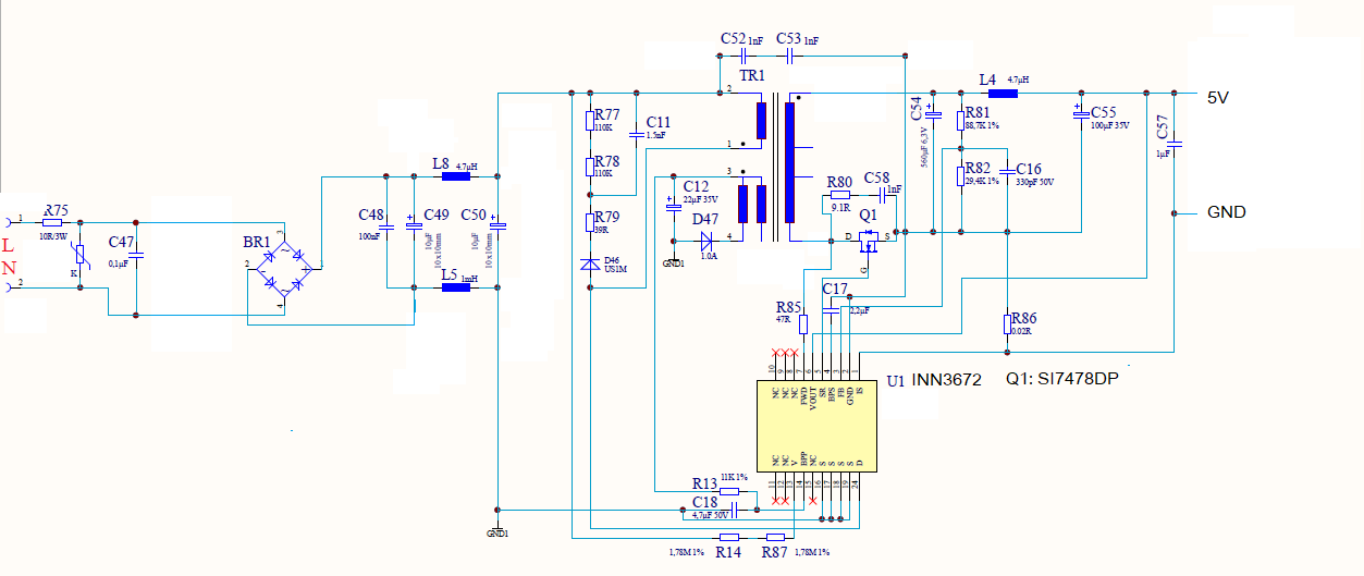
we have a power supply 5V 1,5A with INN3672.
It is working with no load up to 10 mA normally and above 20 mA up to maximum of 1,5A as well.
But between 10 an 20 mA load it keeps restarting.
Do you have an Idea what could be the problem?
best regards Thomas
Comments
Hello PI Nanoe,
thank you for your fast response.
i tried to shorten L4 but that made no difference to the effect.
Here i attach some waveforms as you suggested.
best regards
Thomas
| Attachment | Size |
|---|---|
| vout_bps 1.jpg (126.87 KB) | 126.87 KB |
| vout_bps 2.jpg (120.4 KB) | 120.4 KB |
| bpp_ds_2.jpg (124.39 KB) | 124.39 KB |
| bpp_ds_1.jpg (129.56 KB) | 129.56 KB |
Hi Thomas,
At what condition you encountered this issue? Startup only or during normal condition also (every time you change the load to 10-20mA)?
If you may, can you provide us the gerber file of your layout we would like to further review the design on our side. Also the PIXls used, and transformer construction would be highly appreciated.
Regards,
PI-Nanoe
Hello PI-Nanoe,
The problem occurs every time the current drops to values in the area around 10 to 20 mA, not only at startup.
We have this power supply design already in different products. In this particular case (new application) the controller board in our application has a low current (14mA) during startup and then the power supply switches off, so our product fails to power up to working condition.
As a work-around: if we add a resistor which draws 20mA the application starts without problems and works fine.
Our other applications run with other controllers which have higher currents during startup.
Attached you find the PIXls file and the transformer data sheet, as well as the gerber file.
Thank you in advance for the review.
best regards Thomas
| Attachment | Size |
|---|---|
| InnoSwitch3-EP_5V_1,6A_2019_08.pixls (49.11 KB) | 49.11 KB |
| Transformer 1.png (266.51 KB) | 266.51 KB |
| Transformer 2.png (369.34 KB) | 369.34 KB |
| 2024_11_06_Gerber PCB 270423-1a.zip (142.24 KB) | 142.24 KB |
| PCB bottom.png (45.33 KB) | 45.33 KB |
| PCB top.png (48.66 KB) | 48.66 KB |
Hi Thomas,
I have some comments regarding the design. I think, it is best to optimized first the design especially the transformer. Please see attached file for the comments.
While optimizing the design, you can try adding a feed forward network across the feedback resistor. See image below for your reference.
Regards,
PI-Nanoe
| Attachment | Size |
|---|---|
| feedforward.png (23.07 KB) | 23.07 KB |
| Forum_INN3672_keeps restarting at very low load_design comments.pdf (642.48 KB) | 642.48 KB |
Hi PI-Nanoe,
thank you for your review.
The feed-forward network did not make a difference.
Im afraid i sent you the wrong PlXls file.
The design is already a few years old. I remember that the FAE of our PI-distributor made the design for us because we needed to choose a EFD20 core due to mechanical reasons (lower profile)
So i don´t have the actual PlXls file.
we received a few more devices which failed production test.
When i look at startup i see an overshoot on the output voltage (see attached screenshot of the oscilloscope) . I think this leads to an OV failure which stops the switching and causes resart.
Overshoot is the same when i short the post filter inductance. What can we do to prevent the overshoot?
Best regards
Thomas
| Attachment | Size |
|---|---|
| overshoot on Vout.jpg (134.4 KB) | 134.4 KB |
Hi Thomas,
This is unusual behavior. I strongly recommend optimizing first the pcb layout regarding this. The effect of stray inductance (pcb layout trace is not properly implemented) may cause this issue. Can you try also shorting the Is resistor (R86).
Regards,
PI-Nanoe
Hi Thomas,
Can you try shorting first the L4 in your schematic or connected the Vout pin directly to the node of C54 (see attached image for your reference)?
If you are using post filter, Innoswitch voltage sense resistor should be connected before the filter inductor.
If this does not resolve the issue, can you please provide us the capture waveform of the following during the transition of the normal operation to auto-restart.
- output voltage
- bpp
- vds (innoswitch)
- bps.
Thank you.
Regards,
PI Nanoe