
Incorrect operation of constant power in InnoSwitch3-CP H202
Good afternoon!
In my device, the constant power function does not work correctly. After the output current is compared
with the calculated current (pin IS), the voltage drops and the current drops. What can this be related to?
コメント
Hi PI-Spark!
1. Rated value of my power supply VOUT=24V, IOUT=1.75A;
2. I use a resistor rated 0.005 Ohm;
3. VOUT start to fall at the load current 1.56А and current is falling;
4. The load current in my power supply does not become constant. At VOUT=6V and IOUT=1.89A, then the current increases as the load increases. The chip goes into AR mode at VOUT=3.45V and IOUT=2.43A.
Thanks!
Hi Ensider,
Thanks for providing the data.
Can you confirm the part number and Feature Code (H2xx) of the Innoswitch3-CP device you are using?
Also in the PCB layout, is the current sensing resistor kelvin-connected into IS and GND pins?
In constant current operation, IS and GND pins will regulate at ISV(TH) = 35.9mV typical.
If the effective resistance seen by the IC is much larger then it would affect CC regulation.
Once CC regulation is accurate, it will follow that Constant Power profile will also be as expected.
Also to clarify, is the Constant Power profile you need is 42W, similar to attached image?
Regards,
PI-Spark
![]()
| Attachment | サイズ |
|---|---|
| CV_CP_CC_0.png (26.39 KB) | 26.39 KB |
Hi PI-Spark!
I use a device INN3268C, part number INN3268C and Feature Code H202.
In the PCB layout, is the current sensing resistor kelvin-connected into IS and GND pins.
In the PCB layout, the current sensing resistor connected into IS and GND pins.
Yes, I need is the Constant Power profile is 42W and is similar to attached image.
What do you mean by effective resistance and where to look for it for my device?
Hi Ensider,
Thanks for confirmation.
What I meant in the previous reply is, if the current sense resistor (5mohm) is not kelvin-connected in the layout to the IS pin, then the total resistance across IS and GND pins that the IC will sense would be 5mohm + few mohms of trace resistance.
Can you also share the Schematic and PCB layout of your design?
Is the behavior similar at low line input and high line input?
Hi PI-Spark!
Are you saying that the current sensing resistor must be connected to the IS and GND pins with 4 trace? In order to exclude few mohms of trace resistance?Can you send me a Schematic and how it is implemented on PCB.
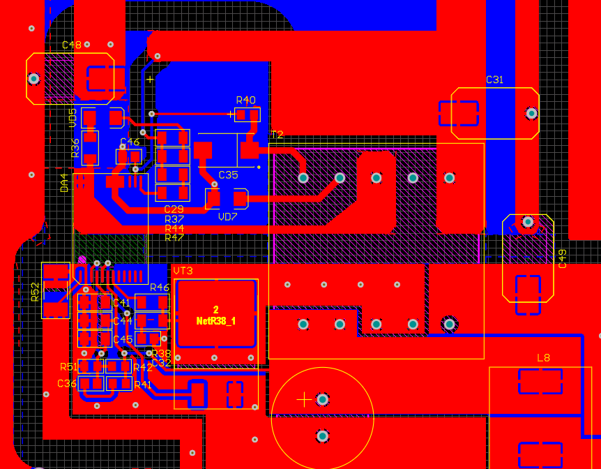
Attaching at Schematic and PCB layout of my design.
The behavior at low line input and high line input is the same.
Thanks!
| Attachment | サイズ |
|---|---|
| PCB layout.PNG (88.68 KB) | 88.68 KB |
| Schematic_3.PNG (83.3 KB) | 83.3 KB |
Hi Ensider,
Sorry for the late reply.
Have you check InnoSwitch3 Family Application Note below for layout guidance?
https://www.power.com/design-support/application-notes/an-72-innoswitch3-family-design-guide
There are also design examples in the InnoSwitch3-CP page
https://www.power.com/products/innoswitch/innoswitch3-cp
Regards,
PI-Spark
Hi PI-Spark!
Sorry for the late reply.
Yes, I did. Could this be due to a faulty PCB layout?
I've looked at examples of the design many times, too.
To date, I have been able to achieve a smooth change in output voltage in CP mode, but the current still does not increase, more than the value of CC, the value of which is set by the current-sensitive resistor IS.
Thanks!
The problem was solved by replacing the transformer!
Hi Ensider,
Thank you for using products from Power Integrations.
Can you share more details on your design?
Regards,
PI-Spark