
TNY285DG - random output regulation issue
Hi there,
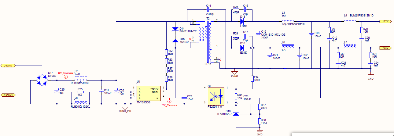
I have implemented a power supply for our product based on the TNY285DG device using PI-expert 9.1.6.3.
Input voltage range is 180V to 265V, outputs are 12V (250mA) and 17V (250mA), regulation is derived from the 12V output. The loads are not contstant, however the schematic includes load resistors to ensure 15% minimum load at all times.
An initial production run of about 500 units has been done which has revealed a problem that I never detected during the prototype phase where I built about 13 units.
The problem only occurs on about 4 percent of the power boards, the rest behave absolutely correctly.
The problem that occasionally occurs on random boards is that the 12V DC output sags to about 11,3V and appears to 'float' around unregulated at certain mains input voltages. I have the unit connected to a variable AC source (Variac) and the issue is clear when doing a sweep of the mains input. The DC output is regulated at 12V at 150V to 180V, then at 200V, the DC voltage will drop to approximately 11.3V, float and fluctuate, and then rise back to 12V at 250V. These are typical values noted, although I have noticed some of the units where the output voltage fluctuates around 11,3V or so at 230V mains input.
I've tried changing the optocoupler and adjusting the bias currents, but none of these made a difference.
I discovered, by accident, that the problem completely disappears and perfect operation occurs on all faulty power boards if I place an oscilloscope probe (completely disconnected from the scope!) across the source and drain contacts (pins 4 and 5) of the TNY285.
The problem now is that I cannot capture the problem as it vanishes as soon as the scope probe is attached to the circuit!
Any ideas as to what may be causing this issue?
Many thanks,
Gary
Comments
Hi Leo,
Thanks for the response and the questions.
I have some observations which I will address after I've answered your questions:
1. Are the failed boards, all exhibit regulation problem? coming from the initial 14 units with no problem at all I wonder first and foremost if the transformer construction and all is constant for the next 500 boards. For the first 13 units, are the transformers built in the factory or is it initially made by the designer (let's say you as the design engineer)? Because basically, for these designs, the engineer is the one who builds the transformer first for the first few prototypes just to make sure everything is done correctly. As soon as he was able to qualify and test that such design works properly then it is endorsed to manufacturing for some initial run of units. I am suspecting that there might be some problem or issue with the uniformity in transformer construction.
The problem occurs on only a few boards off the production line. We engaged Elytone to manufacture 20 sample transformers in total to the design specified by PI Expert. I do not have the experience, equipment nor materials in order to wind suitable transformers. All of the sample devices appeared to operate satisfactorly when in circuit. I expect there to be manufacturing tolerances in the transformers which may account for the randomness of the issue.
2. In the affected units, is there a chance that a value in the overall components is not correct? like there had been some wrong placement of values for the components say resistor or capacitor. Sometimes these problems occur in the manufacturing area causing some issue for some units.
I have inspected several of the 'faulty' boards and all are correctly assembled.
3. When you do put a probe (but disconnected in the scope) the drain voltage, the unit works accordingly. With that am suspecting this might also be a case of noise or grounding issue. Since there is no captured waveform for this for now we can only suspect some possible cause of the issue. By the way I noticed that you do have multiple winding in the primary, not sure about it but am assuming these are cancellation winding for EMI purposes.
We have EMI cancellation windings on the primary. Our product has passed EMC certifcation to CISPR 22 class B.
4. If the "good" unit transformer was transferred to the "bad" unit, just basically replace the bad one with a good one, is the issue still there? If the issue is gone, again we may probably look at the overall transformer construction.
I tested 25 random transformers in a 'faulty' board and put aside several that seem to operate incorrectly. Placing some of these transformers into another board, in some cases, showed correct operation and for others, incorrect operation.
5. If the bad unit controller, TNY, is transferred to the good unit, is the issue still there?
I replaced the TNY on a faulty unit and changed the feedback opto coupler, no change in operation.
6. Is the sweep that is being done fully automated? or is it being done manually? am also suspecting some test set-up issue causing some problem on the unit.
The AC sweep is done by hand by turning a Variac, or variable AC transformer. I have two variacs in different test areas which both show the same behaviour on faulty boards. I do not suspect a grounding issue at this stage.
I did some investigation of this issue using a board which allows the easy removal and swapping of the transformer.
I confirmed the 'scope probe' fix by soldering a 15pF 1kV ceramic capacitor across the TNY switcher MOSFET S-D. The regulation of the circuit was perfect over the whole AC input range. Removing the capacitor returned the board to incorrect operation.
This got me thinking that perhaps this is a resonance or ringing issue caused by transformer parasitics in combination with diode capacitances.
I removed the 15pF cap and focussed my attention to the components on the secondary side of the transformer.
My power supply has a 12V and 17V rail, the 12V rail has a permanent dummy load on the PCB, the 17V rail does not and is very lightly loaded. Some reading up on flybacks indicated that lightly loaded outputs other than the main loaded output of a flyback may cause ringing problems due to parasitics in the transformer.
Afterwards, my attention turned to the snubber across the 17V rectifier diode. Applying a scope probe (connected to a scope this time!) indeed revealed significant ringing after the diode turn-off time. I increased the capacitance from 22pF to 1000pF and the regulation of the board came right and operated perfectly over the AC input range. I reduced the value of the cap to 220pF and the operation was still correct.
I'm not sure why PI Expert specified such a 'light' snubber, but the answer seems to be in an increased snubber cap, I'm comfortable with a 1000pF cap instead of 22pF. The other great side effect is the the 17V rail, which always hovered at 16,85V on this board is now at 16,95V or so.
The heavier snubber action reduces the ringing significantly in the circuit, so I think it may be the solution to the problem.
I imagine tranformer parasitic tolerances from unit to unit affect the rigning ampiltude from board to board - some work, others don't.
I'm interested in your thoughts on the above observations?
Kind regards,
Gary
Hi Leo,
I've checked the responses of the circuit using 270pF snubber caps and have found that the regulation is operating correctly over the mains input range and under load by the rest of the circuit.
The 1000pF caps may lead to more power dissipation in the snubber resistors than they can handle, so I'll stick with the 270pF instead.
Are you comfortable with this modification to the circuit?
Kind regards,
Gary
Hi Gary,
It's good to hear that the design is now working perfectly. I am just wonder how the ringing looks like to assess how it affects regulation. Am assuming the ringing is in the VDS rising edge that is needed to be snubbed so as not to exceed the maximum voltage across the diode. I wonder how it affects the regulation. If the snubber is not present, and say the diode is replaced with a PIV will the regulation still have problem? No worries, it is just a question about proof of concept not necessarily needed to be performed. To answer your question about the snubber from PI Expert, kindly take note that these are just starting values. Especially for snubbers which rely heavily rely on parasitics depending on layout and transformer design. I must say as long as your efficiency is still good with the selected value of snubber capacitance then that will do the job already. Kindly take note that you must reverify the EMI scan for the new capacitance value. I suppose it should be better if not the same since the peaking are lower. It is ok to adjust the value of the snubber with respect to actual application against the PI Expert since again this there is always a variation (to add more is the transformer construction which adds parasitics as well). As for PI Expert there is a determined parasitics already for computing the snubber value. This should come as a general starting point or guide and tune accordingly when needed. Lastly may I also suggest to verify the drain to source voltage of the primary. Just make sure the snubber ciruit is also sufficient. Congratulations. :)
Leo
Hi Gary,
Good day, the problem seems peculiar and hard to detect coming from the premises. Just a few verification:
1. Are the failed boards, all exhibit regulation problem? coming from the initial 14 units with no problem at all I wonder first and foremost if the transformer construction and all is constant for the next 500 boards. For the first 13 units, are the transformers built in the factory or is it initially made by the designer (let's say you as the design engineer)? Because basically, for these designs, the engineer is the one who builds the transformer first for the first few prototypes just to make sure everything is done correctly. As soon as he was able to qualify and test that such design works properly then it is endorsed to manufacturing for some initial run of units. I am suspecting that there might be some problem or issue with the uniformity in transformer construction.
2. In the affected units, is there a chance that a value in the overall components is not correct? like there had been some wrong placement of values for the components say resistor or capacitor. Sometimes these problems occur in the manufacturing area causing some issue for some units.
3. When you do put a probe (but disconnected in the scope) the drain voltage, the unit works accordingly. With that am suspecting this might also be a case of noise or grounding issue. Since there is no captured waveform for this for now we can only suspect some possible cause of the issue. By the way I noticed that you do have multiple winding in the primary, not sure about it but am assuming these are cancellation winding for EMI purposes.
4. If the "good" unit transformer was transferred to the "bad" unit, just basically replace the bad one with a good one, is the issue still there? If the issue is gone, again we may probably look at the overall transformer construction.
5. If the bad unit controller, TNY, is transferred to the good unit, is the issue still there?
6. Is the sweep that is being done fully automated? or is it being done manually? am also suspecting some test set-up issue causing some problem on the unit.
Hope to hear from you soon so we can address this issue properly.
Regards,
Leo