
Question some thing with LNK306 schematic
I want using LNK306- 225mA for my project and i'm find some schematic, but some thing im not understand and want help.
+ Note 1 : With desire EMI filter, what inductor we using for good PCB, I'm see some example : 1mH,5mH ,6.8mH...... ??
+ Note 2 : I'm not understand "structure schematic" in note 2 , Can you explain me understand ?
TY for reading.
Comments
Hi Pl-Pike,
Thank you for comment, i will try with Note 1.
With note 2 : Im explore 3.75V created by 12V . Im dont know this, this dangerous ??
Hi HoangThinh,
For the note 2: Do you have a schematic of the said circuit? Thank you!
Regards,
PI-Pike
Here :
Im drawing with some component.
| Attachment | Size |
|---|---|
| Schematic.PNG (94.6 KB) | 94.6 KB |
Hi HoangThinh
Could you explain to me what's the application of the whole circuit? Where does R1 connected? Please give me the rest of the circuit so I could understand more.
I think the note2 circuit should be safe.
Regards,
PI-Pike
Hi PI-Plke
This is Power in my product:
Some information:
+ Using LNK306 to ~360mA 12VDC MCC mode
+ 12VDC to 5V
+ 5V using for : ( 3x200mW relay 5V ) + (~150mA 3V3 MCU STM32) + (~500mA 3V3 Led and wifiessp8266) = ~ 2.75 W
Have some problem, this destroy when using after 1 days.
+ Destroy in wire L & N (1mm PCB with wire ) ??
+ IC LNK not destroy
+
Can show me some solution.
+ I want add 10R/2W in wire N for fusible ??
+ 1mm wire L& N to small ?
+ We will wait for your reply.
Thank you.
Best Regards.
Hoang Thinh
Hi HoangThinh,
Did the wire melt? You might want to check the temperature of the input side to see what components overheat.
You can use a Fusible resistor but check the efficiency and its temperature.
Regards,
PI-Pike
Ya it destroy and cap C5 (4.7uF/400V) destroy.
Im fix 2 cap and 1 inductor to 1 cap, any problem ??
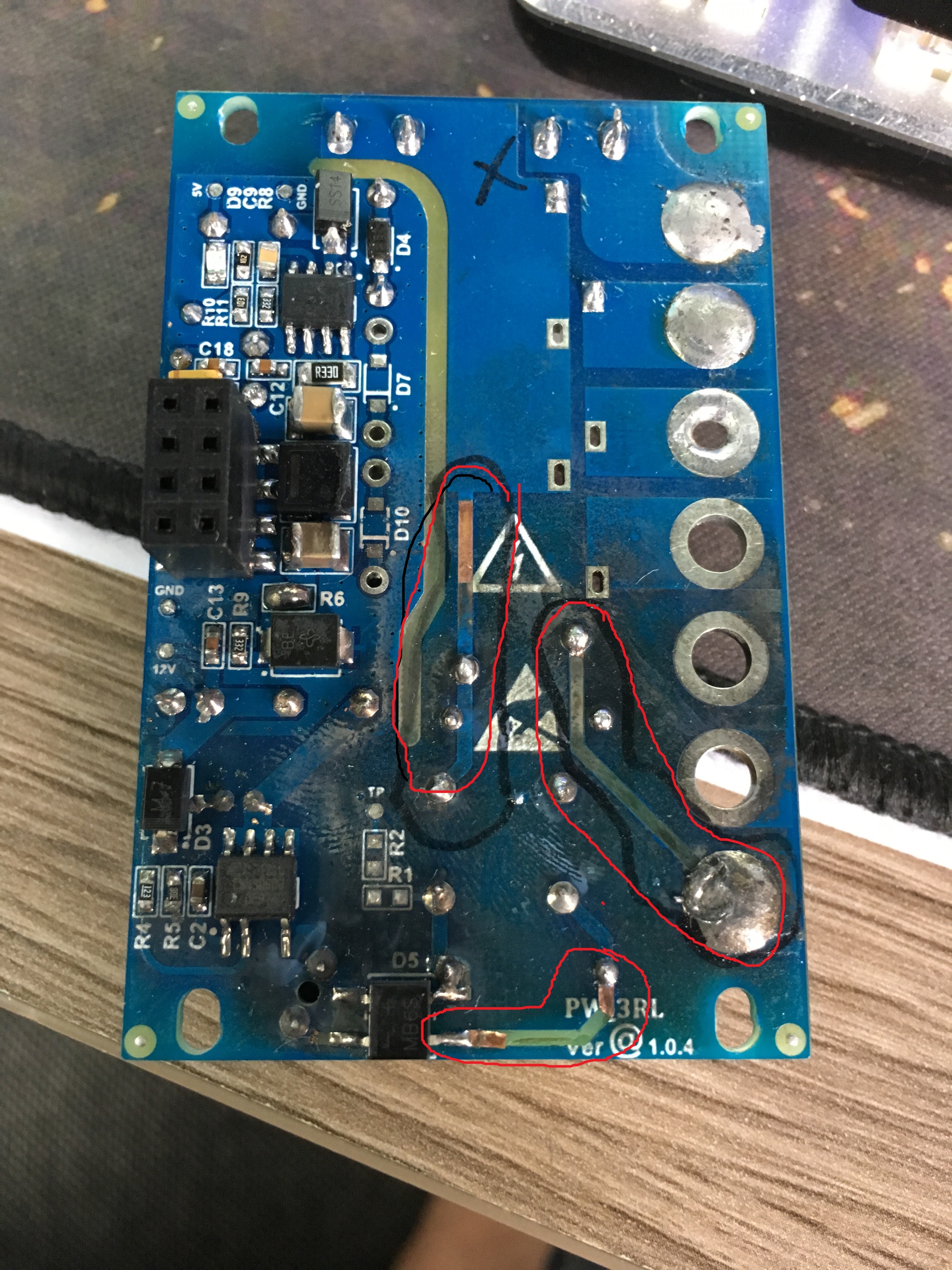
Look picturer with Load is 1 lamp 60W. You can guess problem ?? and how to fix them.
Next I add NTC(5D-7) and Ressistor fusible (10R 2W), and checking soon.
| Attachment | Size |
|---|---|
| IMG_0033.JPG (2.67 MB) | 2.67 MB |
Hi HoangThinh,
Can I know what is your AC Input when that happened?
I think the AC Input Side only what causes the problem. I guessed that the 4.7uF/400V got destroyed first. May I know what's the part number/datasheet of that capacitor used?
Also can you send the top side picture of the device? Thanks!
Regards,
PI-Pike
Hi PI-Pike
- Yes i think too, i build 9 board power for dev and 1 of them destroy and 8 board run ok, its 2 week. :((
May this capacitor so bad, i'm buy in shop in near my house,it have 4.7uF/400V and no datasheet . You have any recommend for capcitor ?. I'm reading in App Note AN37 talk "2uF/1W output" , this my device about 1.8W. I think its ok .
- This full 2 side board destroy:
- Now, i'm build new design with some add component and test them more. Look in schematic.
+ Before im not use C6 and L2 and now i add them and unsing 1.5 mH replace for 1mH in L1 and add RT (10R 2W)
+ I think before im not use this so C7 destroy. Pls check for me, this is ok ?
TY for reading and checking.
Regards,
Hoang Thinh
Hi Hoang Thinh,
What input voltage did you use?
Choose a good brand of capacitor. Nichicon/Rubycon are my suggestion. Also the rating of the capacitor should be also enough.
Yes the 2uF/W is correct. So 4.7uF capacitor should work fine. If you want to add L2 you can divide the 4.7uF capacitor into two 2.2uF capacitors. Two 4.7uF capacitor is too much. RT1 is also fine.
Regards,
PI-Pike
Hi PI-Pike
My input V is 220VAC
Oh i dont know 2 cap 4.7uF is much. Im testing with new design. About 2 days and it work file. After i will replace 2.2uF
TY.
Regards,
Hoang Thinh
Hi Hoang Thinh,
You're welcome.
Regards,
PI-Pike
Dear Pl-=Plke,
Good Day !!
Sorry I am posting something not related to this Chip.
I am Using the LNK6428K its 5V, 2A design.
As per the design its not giving 5V output its giving only 4.4V but as per the application note and data sheet load regulation will be in the range of +/-5% i.e 0.25V.
I attached application note schematic and Tx design.
| Attachment | Size |
|---|---|
| smps_1.PNG (63.17 KB) | 63.17 KB |
| Transformer.PNG (406.57 KB) | 406.57 KB |
Hi eman,
Is it on 2A Full Load condition? Try adjusting the feedback resistors. Increase resistance of R6.
Regards,
PI-Pike
Hello PI-Pike
Now we have some problem with LNK306 power.
When i using them for touch sensor, this is stuck and not work good, but using any power difference it work fine (adapter...).??? what problem?
+ And if i connect wire GND power LNK306 with GND adapter, touch work and cut it fail
+ After i research and look some schematic and add C80 in schematic. it work , touch sensor ok. :D
And can you explain phenomenon for me ?? and it dangerous , i'm testing 2 days and work fine but this first time im add and see this cap in schematic and reference design not note that.
Look in schematic.TY
Best Regard.
Hoang Thinh
| Attachment | Size |
|---|---|
| 123.PNG (66.94 KB) | 66.94 KB |
Hi HoangThinh,
Where did you put the C80 capacitor? Care to explain what is this touching sensor for? Thank you!
It might be the noise that affects your device so that putting a capacitor filters the noise, thus solving the problem.
Regards,
PI-PIke
Hi PI-PIke
Im sorry too late read comment from you. Some busy.Let me explain something.
When i using this design power LNK306 for touch sensor. It work not good, it stuck and sometimes no work. But when i using any difference power : adapter... It work normally. And after i connect 1 wire GND form power adapter it work normally. I dont't know why??
After im reading some datasheet, touch sensor need some capacitor connect earth ground. And i think adapter have. And im find some schematic connect earth ground with LNK306. I will try 1000pf/1kV(connect between pin S and GND - look schematic im post before) and it work, but some problem more :
+ The inductor sound to large and it hot more than normal. But it work with touch sensor :D.
LNK306 can work with touch sensor ?? And you have some solution for this problem ?
Oh! In addition, im look datasheet LNK3206 , and it recommend using more than LNK306. LNK3206 work good ?
| Attachment | Size |
|---|---|
| Touch with capacitor (29.63 KB) | 29.63 KB |
| Cappacitor with GND (211.44 KB) | 211.44 KB |
Hi HoangThinh,
The capacitor C11 on the 2.PNG you send is a Y-cap. This helps for EMI.
Adding the 1000pF across S to GND pin is fine. I think more load on the output when you press the touch sensor therefore the inductor becomes more noisy and hotter. Try increasing the inductance and current rating of the inductor, also if can try increasing the output capacitor capacitance to reduce ripple.
LNK3206 is a newer product / newer "version" of LNK306. Yes it is better.
Regards,
PI-Pike
Hi HoangThinh,
Note 1: You can start at 1mH then start increasing it if you have problems in EMI.
Note 2: I think it's just a voltage divider for Cap C1 to power up some circuit that needs 3.75V.
For example if your AC Input is 265VAC. Then the voltage across C1 will be 22.32V minus the drop of D1. Then will discharge the voltage across C1 to R4 when the AC Input is off.
Regards,
PI-Pike