
Cold start hiccup on TOP265KG
Hi,
I generated a design on PI Expert for a rough test on a controller I want to bring up. There were a few problems I saw generated by the design that may or may not be my mistake. I have attached a schematic for reference. Layout is by the books and almost 1:1 matches TOP265 datasheet with the exception that I am using SMT parts on this project (the primary switch node connection could be larger and will be on final rev). Note D301 is a DNP placeholder on the board and R310 has been removed.
In initial testing, R310 was causing problems when the output was loaded with 6 ohms. Upon inspection of the Control (C) node, I noticed that control was falling below the 4.8V line and causing autorestart cycles. Removal of the R310 resistor solved that problem and heating of the snubber and TOP265 stay below 75C at all times with a 25C ambient. Not a big deal. I am working on adjusting C304 and R301 to minimize ringing further, but this is a small side problem as my temperatures are good and we are not hitting an avalanche point under max load. Ringing attached for reference.
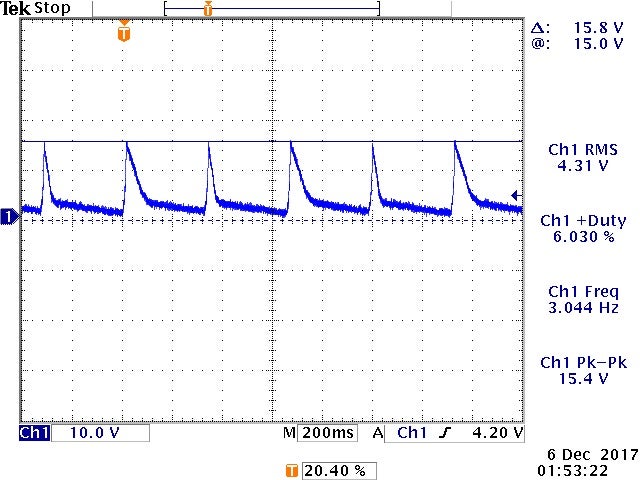
Now, the issue I am seeing at max load only happens initially when the system is cold. When I apply power (through 15A switch, fuse, and FW rectifier circuit), the output will hiccup for about 5 seconds. Once started and warm, this issue no longer presents itself, but if I power things down, then walk away for an hour, this issue is repeatable. I have inspected the (C) node during this event and again, I am seeing the (C) node drop down to 4.8V for these cycles.
See attached hiccup/autorestart image.
I suspect there is a gain issue of the U301/R306 combo so I have been adjusting R306 downward to 6.8k/5.6k. My problem is that the nature of the issue makes testing and verifying this very time consuming and tedious.
What ideas do you PI experts have and is there an issue with what was generated online? It would be nice to know why R310 disables my output at any kind of load since it should strap us slightly above 1.5V across the diode of U301.
Nick
Comments
Kryton,
Thank you for the reply. I am actually re-evaluating this section of the design. Some of this ringing is causing some USB upsets downstream when I run the motor on the line side of the converter. There is no ringing on the power stage of the motor controller and the system runs normally when a lab supply generates this isolated +15V. My current target is quieting the EMI on this converter.
The transformer in use is the Pulse PH0270-NL (876uH primary and max leakage of 28uH).
Ringing here is pretty substantial, so whatever advice you may have would be appreciated.
Nick
| Attachment | Size |
|---|---|
| xformer_PI-Ex.pdf (1.2 MB) | 1.2 MB |
Hi Nick,
We have an application note AN-15 TopSwitch power supply Design techniques for EMI and safety that you could refer to.
You will find that adding a transformer shield /cancellation winding between the primary and secondary and connecting one end of it to the source pin reduces the capacitance between the layers and thereby, reduces common mode emissions. A flux band over the outside of the transformer also serves to reduce common mode emissions.
Hope this helps.
Best Regards,
PI-Kryten
Kryton,
That advice is appreciated as always. My other primary question was rooted in the OP. There is a lack of functionality observed when R310 is populated. Is there a reason for this resistor addition outside of clamp/filtering?
Nick
Hi Nick,
Can you please share the PI-EXpert file with me? I do not think R310 is required..
I would like to verify this.
Best Regards,
PI-Kryten
Kryten,
I have exported to excel from PI Expert and attached, though I am unsure if this is what you want.
I am curious if the gain wrapped around this optocoupler (U2, refernce attached) is what is causing startup instability, hiccup, but in testing I have been sequencing each system in this design to remove hard load transients/upsets to eliminate the issue.
I walked down the value of R10 to about 5.6k to help startup transient as well.
Thoughts?
| Attachment | Size |
|---|---|
| Lower.zip (82.89 KB) | 82.89 KB |
Hello Nick,
Thank you for the interest in using Power Integrations product. We really appreciate your focus and patience in sharing all the detailed technical discussion with us.
The R310 in your schematic is used to supply TL431 Minimum cathode current for regulation (0.4mA to 1mA) based on TL431 datasheet. in this way, we can reach better regulation for the output.
As you mentioned, it looks like with R310, there is no functionality observed. You mentioned you see C pin even went below 4.8V. All these information points to the current into the C pin is really low. Can you verify if the optocoupler PS2501L-1-K is functioning right, especially the CTR is at the range of 300 to 600. i am wondering if the CTR somehow is low and cause the current into C pin not enough.
By the way, what is your input voltage range from the FWRect and what is your output power requirement for your design?
The schematic look OK from me. if you can give us more information about what is the requirement you put into the PIexpert when creating the design. it would help us a lot to figure out a way to help you solve the issue.
best Regards
PI-YY
The input voltage range is running at 110VAC plus whatever line deviation is. I see about +170VDC at the Cap bank output that is the +FWRect node.
I have seen this across several units and have tried replacing the TL431's and PS2501L's to see if replacing them would make a difference. In the end elimination of R310 and decreasing R306 helped the startup condition, however, I do see a startup hiccup from time to time if the output is loaded. In order to minimize the hiccup, the system that uses this supply now sequences power to minimize the load at startup (this is not a problem once the system is in regulation).
Nominal load is 1.8ADC at 15.5V with a startup surge around 2.5A from what I am measuring with a 100kHz probe.
I am not the best at magnetic coupling, but it appears that the auxiliary winding should have enough oomf to keep C from dropping aside from the optocouple gain stage, however, whatever guidance you may provide is welcome. ^_^
Thank you.
Nick
Hello Nick,
From all the information you provided, i agree with you it looks like the R306 is too high. You can reduce this value to make it work.i still suggest you keep R310 as the supply of TL431.
I think the problem here is when you run the PIexpert, you put 15.5V and 2A. can you try to connect a load of 2A which means 8ohms resistor to see if you have this problem or not. i see you check the performance with 6ohms load which is higher than the desired PSU.
if it is not easy to verify the stability and loop gain with the reduced R306, you can also rerun the PI expert and see how much the PI expert is suggesting with 2.5A output. In this way, you can find the complete and right solution from PI expert and then verify on bench. i think with the change of right output power, you should be able to make it run properly
Best Regards
PI-YY,
I got around to testing this out. I have the same hiccup with 2A load in the actual system.
If I change things in PI expert, the gain stage appears fixed at 8.87k gain set with 1k bias. This is true for 2A, 2.5A, and 3.0A. I see some gap warning on the core, but I am ignoring since the transformer I have does not appear to be saturating (at least in terms of shunting, reflected impedance, etc). It may be possible your calculator on PI expert has some internal limit I am hitting.
Keep in mind the current system I am utilizing has a gain set resistor of 5.6k and the bias resistor is left out. I see best performance in the real world with this configuration. I am going to try slightly lower values of the gain set and leave the bias resistor populated today.
Nick
PI-YY,
Experimentally, I have added the 1k bias resistor back into the system and increased the gain set resistor from 5.6k to 8.87k as advised in the PI-Expert design file.
What I am seeing is what I recall when I first played around with this design. The bias resistor causes startup hiccups at low load and continuous hiccups at high load (2-2.5A).
One thing to note in the attached plots. higher gain set resistors generate less overshoot under low loading conditions, so ideally the 8.87k would be used to minimize overshoot, however hiccup occurrence decreases with lower gain set resistors (5.6k and 6.8k).
See attached plots.
Nick
| Attachment | Size |
|---|---|
| 5-60k_with_bias_1k_and_2A_load.jpg (97.02 KB) | 97.02 KB |
| 5-60k_with_bias_100mA_load.jpg (96.62 KB) | 96.62 KB |
| 8-87k_with_bias_1k_2A_load.jpg (94.22 KB) | 94.22 KB |
Hello Nick,
I also run the PI expert and got the same result as yours. The design looks normal to me. The performance you got might need further detailed debug. If possible,I recommend you contact our local field application engineer to support. They can come to your office and do more detailed check. Below is the address you can find the local support.
https://ac-dc.power.com/sales/
Meanwhile, if the removal of the 1K bias resistor can resolve your problem, it is also OK to remove it. The need of the bias resistor is to bias the TL431. if you can accept the regulation performance, the 1K bias resistor is OK to remove.
Best Regards
I will follow up with them.
One thing that bugs me about the generation in PI-Expert wrt to the 1k bias..
I do not see a need for this bias resistor. All the resistor is doing is removing/sharing current from/with the opto-coupler diode. Without this resistor, the opto-coupler diode would be sourcing the net current to the TL431 anyways. I do not see an immediate need for this part in DC or AC analysis (unless you are assuming the diode will be turning on and off like a switch (which I would not expect given the source of a pre-filtered +15V.
Nick
Hello Nick,
I agree with you. The resistor is to sourcing the current to TL431. without the resistor, the opto-coupler diode is going to source TL431. While we could not control the source current. TL431 needs at least 0.4mA to 1mA bias current, that's why we put 1k resistor here to provide at least 1mA bias current.
Again, if the regulation is acceptable, it is OK to remove the 1k Bias resistor.
best Regards
Hello,
Thank you for considering Power Integrations for your power supply application
Can you kindly share the transformer documentation from PI Expert as well?
Best Regards,
PI-Kryten