
LNK623 Application Problem
Hi,PI Engineers:
I have built 1.5W flyback using LNK623, but I want to know feedback control method of LNK623. As datasheet mentions, the feedback pin is compared with Vfb_th(1.86V). If Vfb>1.86V, the MOSFET in LNK623 will be off state. If Vfb<1.86V, the MOSFET in LNK623 will turn on. My question is that "Does the duty is fixed?". If the duty is fixed, Can I know what the duty is?
Besides this question, if that is convenient, can you give me some application note of LNK623?
Thanks.
Comments
Hi PI-Mallora,
Thanks for your help. However, I still have some questions about on/off control.As you mention "The feedback pin dictates the turn-ON (when below threshold) while peak current limit turns it OFF." Does it means as current limit turns the mosfet off, there is no energy transfer from primary side to secondly side, then the feedback pin dictates the zero voltage next cycle , the feedback pin dictates the turn-ON(Vfb=0<Vfbth). So if I use this control method, does the next switching cycle must be turn on?How to regulate the output voltage?
Besides, if it is convenient, I hope you can give me some simulation files(ex.PSIM) or tell me more details about on/off control. Thank you.
Hi henglee,
Since it is flyback, the energy transfer happens when the MOSFET turns off. See attached file for ON-OFF control illustration. Thanks.
| Attachment | Size |
|---|---|
| ON-OFF Contorl.JPG (65.58 KB) | 65.58 KB |
Hi PI-Mallora,
As the datasheet shows, The feedback pin dictates the AC voltage(no rectifier diode). However, I think the picture you that you illustrate is the rectified output voltage. I think the output voltage reflected to FB pin is the square wave. So when the mosfet off, Vds of primary side is zero, then the reflected fb voltage is equal to zero. As the mosfet off, does the next cyle must turn on?Then how to regulate the output voltage?
Thanks.
Hi henglee,
The controller is only monitoring the feedback during flyback so it just monitors the threshold when to turn-ON for the next cycle. When primary mosfet turned OFF, the stored energy in the transformer is delivered to secondary causing the peak voltage then decay due to load. This is also what is being seen by the feedback pin since it is in-phase with the output winding.
Hi PI-Mallora,
I really appreciate your help in resolving the problem.In fact, I'm trying to use PSIM to simulate on/off control method. As you can see in the attachment, there are LNK623 typical circuit and
the Vfb,VDS waveform from simulation. So I'm confused about "Is the Vfb reflected from not Vo but Vs1?" Furthermore, because the Vfb dictates the voltage larger than Vfbth at previous
cycle, The MOSFET turns off at toff.Then Vfb dictates the zero voltage at this cycle so that the MOSFET will turn on next cycle. However, if it is ture, it means the MOSFET must turn off one cycle, and turn on at the next cycle. I think it is wrong. As a resut, I want to know how LNK623 samples the Vfb.
| Attachment | Size |
|---|---|
| waveform.jpg (180.36 KB) | 180.36 KB |
Hi henglee,
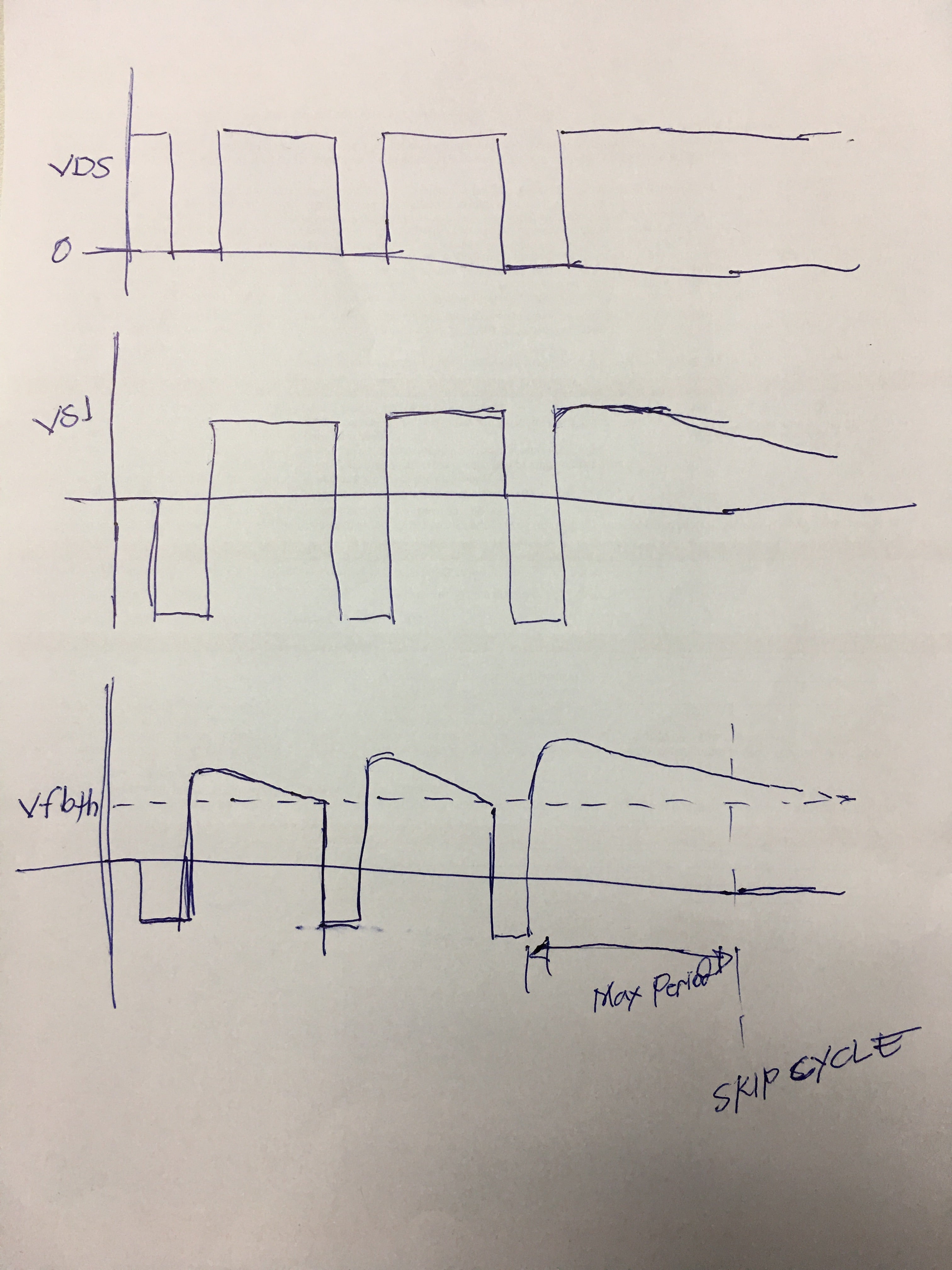
Vfb should be in-phase voltage of the VS1. At normal flyback condition (MOSFET OFF), the feedback goes above the threshold then it will decay and hit the threshold which signal for next turn-ON. At no load or lighter load, it will have skipping cycle/s when it didn't hit the threshold at maximum period since it takes longer time for the output to decay.
| Attachment | Size |
|---|---|
| ON-OFF control.JPG (1.44 MB) | 1.44 MB |
Hi PI-Mallora,
I still meet some problem when testing the flyback circuit. The output voltage will rise to 60 V at no load condiction. I have tried adding the resister across Vo that provides a preload to maintain the output voltages within their respective limits when unloaded. It is effective but decrese the efficiency. As a result, Is there another way to solve the problem but doesn't decrease the efficiency?
Thank you for your help.
Hi henglee,
Putting a zener diode on the output is possible in such a way that it will not conduct at your nominal output voltage regulation. If your output voltage is 48V, you can put 52-55V zener diode so that it will clamp and will not rise much when unloaded but won't affect the efficiency when loaded.
Hi,
Could you please share your design of ON/OFF controller in PSIM? I'm a beginner and finding it tough to proceed. I want to simulate a link switch(LNK 362), hence I need to use an on/off controller. Please help me.
Thanks.
Hi Raveena Kusumanchi,
I honestly don't have the PSIM model for simulation, sorry for that. Maybe hunglee can share his model. Thanks.
Hi henglee,
Good day. Thank you for using Power Integrations' part.
Regarding your question, this is an ON-OFF control not a PWM control. Once it reached the peak current limit, the controller will turn OFF the MOSFET. The feedback pin dictates the turn-ON (when below threshold) while peak current limit turns it OFF. In essense duty is not fixed, it varies depends on the input voltage since it is the variable that changed and dictate how long it will reached the peak current limit from turn-ON. See attached application note for detailed information and for your design guidelines. Thank you.