

LNK364PN Power supply stop work
Nowadays I am trying to complete a smps design with LNK364PN.
My design is used PI expert, You can find related information below:
EE13, Lpri=1.2mH
Vds_peak=470V@220VAC input
Total Out Power: about 1.2W
Output Voltage: 15V0.04A, and 10V0.05A
Input Voltage: 260VAC
Ambient temperature @1.2W load =65C
Feedback: PC817C + TL431.
Fault description: in the Ambient temperature of 65 degrees, the continuous aging of the motor for 2 days, found that the motor stopped, and later on the technical analysis of the driver, it is concluded that the switch power does not work. Further measurement data: FB pin voltage is about 1.65V, and BP pin voltage is about 5.9V. Drain Pin have occasionally PWM chopping action. (After replacing LNK364, Power supply is OK)
I think: LNK364 can not be successfully auto-restart.
Why would LNK364 be broken???
评论
Hi , PI-Mallora
Thanks for your reply . Please check the attachment for details.
| Attachment | 大小 |
|---|---|
| sch.png (20.6 KB) | 20.6 KB |
| pcb.png (19.43 KB) | 19.43 KB |
| EE13-Simple-Test.png (14.83 KB) | 14.83 KB |
| LNK364_V120_Sim.uds (773 KB) | 773 KB |
Hi yanghooyak,
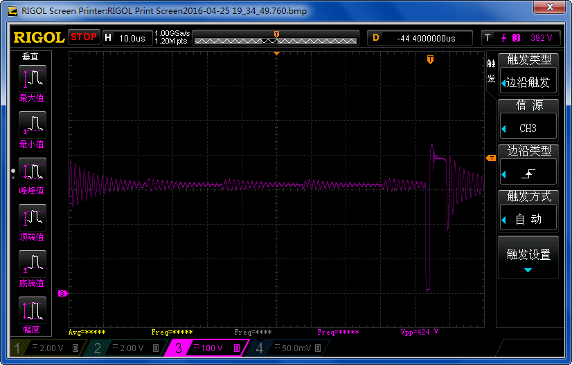
Thanks for the information. Looking at your schematic, it seems that you have forward operation instead of flyback. Can you give me a waveform with VDS voltage and D12 current or voltage at the same time. When you get D12 voltage instead of current, please have the positive probe at the cathode then negative probe at the anode so we have common reference. When you get D12 current instead of voltage, just follow current direction from anode to cathode. Thanks.
forward operation instead of flyback? Why? What's the difference between my design and the reference design(LNK364_V120_Sim.uds)?
Please refer to the attachment (EE13-Simple-Test.png)
Thanks for your reply . Please check the attachment for details.
Hi yanghooyak,
Basically it is the transformer orientation that dictates the flyback operation. Your secondary winding should be out of phase with the primary winding. So when your flyback MOSFET is ON, your secondary diodes D12 and D13 should be reverse bias or not conductiong. Then when your flyback MOSFET turns OFF, that is the time that the D12 and d13 should conduct in a forward bias. If your MOSFET is ON and your D12 and D13 is also conducting, then your have wrong transformer orientation. You have to interchange termination of your primary winding. Thanks.


Hi yanghooyak,
Thank you for your interest in using Power Integrations' part.
Regarding your inquiry, can you provide me your schematic and probably you can attached your PI Expert design so I can have more information of your design. Thanks.