

LNK306 does not work/ not providing the design output current
I assembled in a breadboard a circuit that theoracly should provide at least 350mA at 5.0V. But when the current achieve 150ma, start a crazy behavior, the current and voltage goes down an up... and not stabilize anymore.
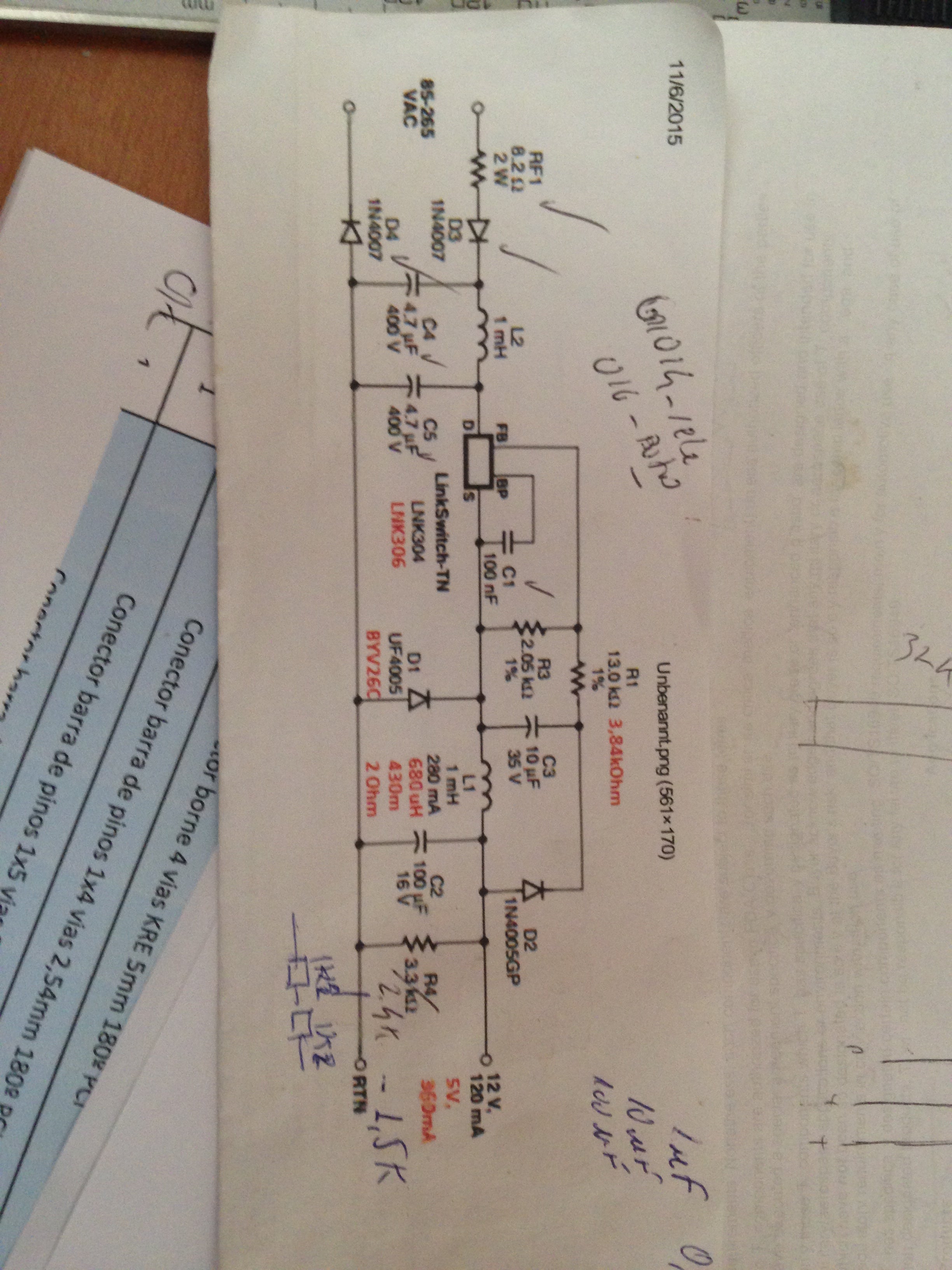
I`m using LNK306, R1 3,9K, R3 2K, L1 680uH (681), D1 BYV26C, D2 UFN4007.. and all other components as the design reference.
What I did wrong? Some idea of the reason for the current is being limited to 150ma?
I did another test.. I made a board instead using breadboard... But the same problem... I load the Power Source using a Arduino Ethernet board W5100 and measure the current.. it´s about 150ma... But when I load with another circuit that draws more... it does not work...
コメント
Hi,
I am sorry for the delayed reply.
Could you please send us the schematic of your power supply, your PIXls/PIExpert design file.
Do you know if the inductor is getting saturated that you are using.
What is the saturation current of the inductor that you are using?
Do you have any drain current waveforms when it was going out of regulation?
Did you try to test the power supply as a stand alone system?
Regards,
PI-NANO
Schematic attached.
I don´t beleive the inductoris getting saturated with that current... less 200ma,
The inductor I´m using should have a 1.3A current saturation
I dont have wave forms.
What do you mean with stand alone system..? I did a test putting 2 x 8ohms resistor (Req=16Ohms) to load around 300ma...
Could you please list some possible reasons for the problem, so I can try change the circuit/components to check.
| Attachment | サイズ |
|---|---|
| IMG_1890.JPG (2.06 MB) | 2.06 MB |
I am using the LNK306 with a 250mA and 3,3 Votlios. The input is universal voltage (85-265) I have three PCB. I have the componenents according with PI xls software. With no load, I measure a voltage of 3,4 Votls. one hour later is about 3,7. but after two days, the voltage is still 3,7V.
When I solder a few componentes (pic18F25J10, a 25LC512, a 74LC138, a few resistors, etc) to the PCB, the voltage drop to 3,1 Voltios.
Whats wrong?
| Attachment | サイズ |
|---|---|
| Screen Shot 2016-02-15 at 09.40.55.png (43.22 KB) | 43.22 KB |
| LinkSwitch-TN Buck 3.3V250mA.pixls (15 KB) | 15 KB |
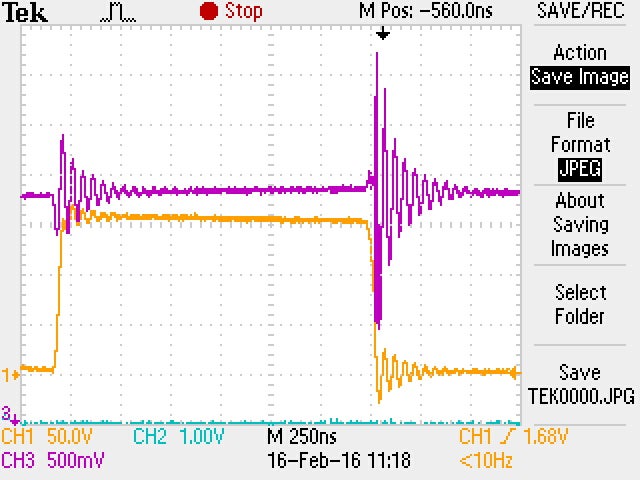
Hello Again. Now, my PS is working in one of the PCB, with all componentes (I have to check the others two). but If a take a look closer with the osciloscope, I can see the voltage is rising up to 4.82V and falling until 2,06 for small period of time. This is normal?
I attatched screen from my oscilloscope with two differentes times. With a multitester , the average voltage is about 3,4 Volts. I changed the rfb resistors for a 2K resistor.
Byt the way. in the graphics, I am measuring the cathode of DFB diode (yellow) and the output (purple)
| Attachment | サイズ |
|---|---|
| V_dfw_V_Out_t_250us.JPG (95.35 KB) | 95.35 KB |
| V_dfw_Vout_t_250ns.JPG (104.49 KB) | 104.49 KB |
Hi,
Do you have your PIxls design file? How did you come up with the value of 680uH? is there any calculation?
At what input voltage does this problem occur? Did you try any other input voltage?
What is ESR of the output capacitor that you are using?
Can you check with very low ESR capacitor and bigger output capacitor to see if the problem goes away?
Unless you have waveforms it will be hard for me to visuvalize whats really going on.
Regards,
PI-NANO
Hi,
From the waveforms I could see that there is lot noise pickup from the probe. How are you probing the output voltage?
You have to use a close coupled probe or barrel probe to minimise external noise pickup.
Since this post belongs to someone else please ask all your questions as seperate post.
Regards,
PI-NANO



The LNK306 is not working and the Techinical support as well.