
LNK306 blows up... sometimes
Hello,
We are using the LNK306 as a non-isolated buck converter. We are on rev1 of the PCB and have experienced a few occasions where the LNK306 blows when the device is powered up. What would cause this typically? High Voltage or high current or both?
We can get a similar failure mode when applying surge voltages to our circuit.
We have tried a number of different tests to isolate the issue, but the results are leaving us even more confused.
Our testing involves using a surge generator device to put high voltage on the input of our design. We have an MOV that is designed to protect the circuit. Fully built boards fail consistently at 4 kV surges. Boards where only the power supply are built up consistently pass at 4 kV.
Tests were done where all components that cross the high voltage/low voltage barrier were removed and the failure still occurred.
Any help or suggestions are greatly appreciated.
Brent
Comments
We have been able to stop the device from blowing up by replacing L2 with 1.0 mH inductor. (It was 470 uH). However, we don't understand why this fixed the issue. Can an FAE explain why this solved our issue? We put a scope on the 5.0V and compared the 470 uH and 1.0 mH responses to pulses and did not see a noticeable difference. We want to make sure we don't accidentally cause this issue to resurface.
Any help is greatly appreciated,
Brent
Hi Brent,
Thank you for considering our LNKSwitch-TN family of devices.
We need to analyze separately the event where you powered-up from a normal input voltage and during the surge high voltage event. To better understand the scenario, can you provide me the following?
1) I need to know the nominal (normal) input voltage with respect to ground that is across C11 and the load current on the 5.0V rail.
2) What else are being supplied with the 5V?
3) Capture the voltage waveform with an osciloscope during normal operation when the board is already powered-up and during start-up across C11, D4 and C12. Get this information from a known good board that never fails and from the unit that blows up. Need to capture waveforms during the failure. You also, need to get the current going to PIN5 for both.
4) Does the board that got damaged always blows up after replacing with a new LNK306?
5) Are all the parts (device name) and the component values the same in all the boards and sure that there are no differences?
6) Kindly explain the power-up sequence. Based from the pictire showing the staus\configuration of the relay, the current sensing cicuit senses the current flowing from the RED to the Black terminal? The supply that goes to the LNK306 comes from the RED and returns to the Neutral? What is the voltage level across the RED and WHITE?
7) What is the level of your surge voltage and where in the circuit did you apply it? Where is the MOV located?
8) What do you mean by these? Please explain further - [Fully built boards fail consistently at 4 kV surges. Boards where only the power supply are built up consistently pass at 4 kV. ] Fully built boards include what other circuits and how do they function in relation to the LNK306 section?
9) What do you mean by this? - [Tests were done where all components that cross the high voltage/low voltage barrier were removed and the failure still occurred.] Components that cross the HV\LV barrier?
Best Regards,
PI-Picard
Hi Brent,
I would have to ask you to provide the details I requested.
Thank you.
Regards,
PI-Picard
Below are the answer to your quesitons...
1) I need to know the nominal (normal) input voltage with respect to ground that is across C11 and the load current on the 5.0V rail.
Input voltage across C11: 1.12V(AC), 161 V(DC) Load current: 46.4 mA
2) What else are being supplied with the 5V?
3.3V regulator, relay coil.
3) Capture the voltage waveform with an oscilloscope during normal operation when the board is already powered-up and during start-up across C11, D4 and C12. Get this information from a known good board that never fails and from the unit that blows up. Need to capture waveforms during the failure. You also, need to get the current going to PIN5 for both.
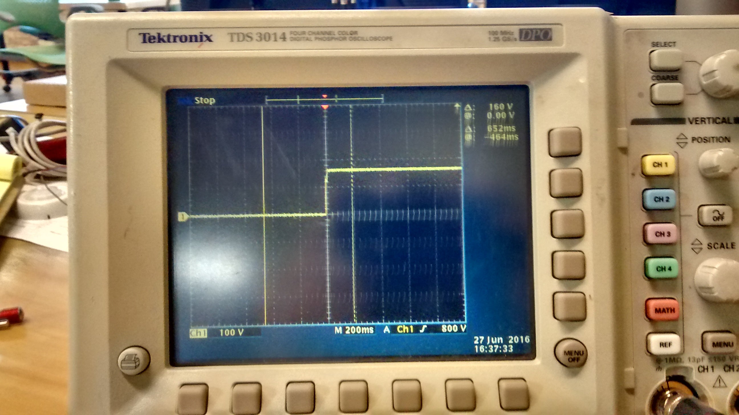
Don’t have a scope to handle the voltage during failure events. Some o-scope images were taken during surges. Attached are images during surges and during start-up for both failing and surviving boards.
NOTE: The oscilloscope results for the transient were measured using a 1k/11k voltage divider to protect our equipment. These are labeled by "(Pass/Fail)_Board_Surge@(+/-)(SurgeVoltage)"
The current going into PIN5 is 1.16 mAmp for both.
4) Does the board that got damaged always blows up after replacing with a new LNK306?
Yes.
5) Are all the parts (device name) and the component values the same in all the boards and sure that there are no differences?
For the failing boards, yes.
The surviving boards featured an inductor, a comparison of the two:
FAILING: 470uH, 0.21A saturation
SURVIVING: 1.0mH, 0.3A saturation
6) Kindly explain the power-up sequence. Based from the pictire showing the staus\configuration of the relay, the current sensing cicuit senses the current flowing from the RED to the Black terminal? The supply that goes to the LNK306 comes from the RED and returns to the Neutral? What is the voltage level across the RED and WHITE?
Yes, the current sensing circuit senses the current from BLACK through to RED (switched hot line, through the relay to control the load). The voltage across RED and WHITE has a nominal 120/277 VAC rating.
7) What is the level of your surge voltage and where in the circuit did you apply it? Where is the MOV located?
The board failed consistently at +/- 4kV transient surges. The surge was applied to the labeled BLACK and WHITE from the schematic. The MOV is located across BLACK & WHITE on the schematic.
8) What do you mean by these? Please explain further - [Fully built boards fail consistently at 4 kV surges. Boards where only the power supply are built up consistently pass at 4 kV. ] Fully built boards include what other circuits and how do they function in relation to the LNK306 section?
“Fully built boards fail consistently at 4 kV surges. Boards where only the power supply are built up consistently pass at 4 kV.” – We made a slight modification to the partially built boards, which was replacing the 470uH with a 1.0mH inductor of a different construction type. This change was prompted by an unrelated fix, but no fully built boards (by the manufacturer) reflected this new component as we believed it was unrelated – not an intuitive fix as they are similarly rated.
We now see that this component change fixed our problem, but the reason WHY is not perfectly clear. The saturation current for the 1.0mH is 0.3A and the saturation current for the 470uH is 0.21A. These values are very close considering the magnitude of the voltage applied.
The fully built boards feature the 3.3V regulator powered by the LNK chip. We also believed this to be an issue but failures occurred with and without the component placed.
9) What do you mean by this? - [Tests were done where all components that cross the high voltage/low voltage barrier were removed and the failure still occurred.] Components that cross the HV\LV barrier?
The current sensing circuit (U9), and the relay (K1) were on the HV/LV barrier. We suspected there was a sneak circuit involving these other two components. Failures still occurred with them removed.
| Attachment | Size |
|---|---|
| Power Integrations Pictures.zip (5.31 MB) | 5.31 MB |
Thank you for those information.
1) Input voltage across C11: 1.12V(AC), 161 V(DC) Load current: 46.4 mA
- Since this 161 Vdc is across C11, I would assume that the Vac input is 120Vac? And that you have only 2 input voltage settings, that is 120Vac and 277Vac right? Or do you have an input AC voltage range?
- The load current of the 5.0V output is only 46mA, assuming that is your maximum load of all the connected circuits, for that low output current you may use LNK302. That will be cheaper. May I ask why did you opted to use LNK306? Is 46mA your maximum load or do you have a peak load requirement that is higher than 46mA?
- Did you use PIXls design tool to help you calculate the values of the components and the inductor value? From the PIXLs that I made using 85-277Vac as the input voltage range, input capacitor equal to 9.4uF, Iout= 46mA and using LNK306, the 470uF output inductor should be ok. See attachments. Because of the failure, I am thinking that probably 46.4mA is not the maximum load. With the output power of less than 1W. You may even lower you input capacitors to 4.7uF. You have to check efficiency, start-up conditions across your operating temperature range, dynamic loading and output ripple.
2) 3.3V regulator, relay coil.
- This relay coil, how big is it? The required supply current to operate the relay?
- If the relay is in that position where terminal 1 is switched to terminal 3, would this mean that the AC mains supply coming from the BLACK terminal is supplying the RED terminal that connects to the external load? If the relay's terminal 1 is switched to terminal 2, there is no AC voltage across the RED and the WHITE terminals right?
- There is always 120\277 Vac across the BLACK and WHITE terminals? The relay need to be switched on to be able to have 120\277 Vac across the RED and WHITE?
- Either relay switch position, it does not matter, the power supply (LNK306) is always on right?
3)
- For the failing\passing board C11, I think you used AC coupling to get the waveform? The waveform across C11 should not decay to zero right? Please use the same o-scope settings as C12.
- Is the C11 waveform taken on the failing boards at start-up? This is what I need.
- Please zoom-in\show 2 or 3 pulses of the D4 voltage waveform. Its not clear, so if possible you may need to get the current through the 470mH inductor at startup on the failing boards.
- How did you measure the current going into PIN5? It is better to check using a small current probe connected to the o-scope.
7) MOV
- Is the MOV rated 910V ac or dc? Since your max AC input voltage is only up to 277Vac, you may try using an MOV rated for 300V or close to it. Do not use MOV with very high rating. 300Vac MOV will be cheaper and will clamp at a lower voltage.
8) “Fully built boards fail consistently at 4 kV surges. Boards where only the power supply are built up consistently pass at 4 kV.” – We made a slight modification to the partially built boards, which was replacing the 470uH with a 1.0mH inductor of a different construction type. This change was prompted by an unrelated fix, but no fully built boards (by the manufacturer) reflected this new component as we believed it was unrelated – not an intuitive fix as they are similarly rated.
We now see that this component change fixed our problem, but the reason WHY is not perfectly clear. The saturation current for the 1.0mH is 0.3A and the saturation current for the 470uH is 0.21A. These values are very close considering the magnitude of the voltage applied.
The fully built boards feature the 3.3V regulator powered by the LNK chip. We also believed this to be an issue but failures occurred with and without the component placed.
- How much load current does the 3.3V draw from the 5.0V output? - In other words what is the power drawn by the 3.3V output at start-up at normal steady state operation?
- For the boards where only the power supply were built, was the relay connected? meaning was the 5.0V output supplies the relay at that time triggering the relay? How big is this relay by the way, (current of the relay)? This maybe causing your failure during start-up where this relay will load additional current from the 5.0V output.
- Try removing the relay, unmount it from the board. Put back the 470uH and power-up the complete fully built board without the relay only.
- Try also, instead of removing the relay, remove the 3.3V regulator from the board to validate which is causing the failure. If the 3.3V regulator is really causing the failure, then this must be drawing a large current from the 5.0V regulator. But, evenso, the LNKSwitch should protect from over power or short circuit conditions.
9) The current sensing circuit (U9), and the relay (K1) were on the HV/LV barrier. We suspected there was a sneak circuit involving these other two components. Failures still occurred with them removed.
- You mean you physically removed the relay from board and still there were failures with the 470uH?
------------
Do this:
1) With the power supply only mounted\built on the board, using the 470uH, remove the 3.3V regulator and the relay. Power up the LNK306. Using an E-load, increase the load current until the LNK306 will enter the power limit. Record the max output current that you were able to load before it goes to power limit. After this, change to 1mH inductor. Repeat the same procedure.
2) Power-up a completely fully built board. The relay, sensing circuit, the 3.3V regulator should be there and use the 1mH inductor. Will it pass? You need to do this to validate the fix. Test in at least 3 boards.
3) Change the LNK306 and use LNK302. You may keep the same input capacitors and use only 1mH. Test in at least 3 boards. If it works reduce the input capacitors to 4.7uF and check again.
4) Send a picture of the complete board if that is ok.
Regards,
PI-Picard
| Attachment | Size |
|---|---|
| LNK306 Buck Design_46mA.pdf (523.43 KB) | 523.43 KB |
| LNK302_Buck Design_46mA.pdf (523.49 KB) | 523.49 KB |
1) Input voltage across C11: 1.12V(AC), 161 V(DC) Load current: 46.4 mA - Since this 161 Vdc is across C11, I would assume that the Vac input is 120Vac? And that you have only 2 input voltage settings, that is 120Vac and 277Vac right? Or do you have an input AC voltage range?
The input voltage range is 120-277 VAC.
- The load current of the 5.0V output is only 46mA, assuming that is your maximum load of all the connected circuits, for that low output current you may use LNK302. That will be cheaper. May I ask why did you opted to use LNK306? Is 46mA your maximum load or do you have a peak load requirement that is higher than 46mA?
Peak load is 200 mA with the relay activated other circuitry placed. The same failure occurs with the relay removed and the other circuitry removed or not placed.
- Did you use PIXls design tool to help you calculate the values of the components and the inductor value? From the PIXLs that I made using 85-277Vac as the input voltage range, input capacitor equal to 9.4uF, Iout= 46mA and using LNK306, the 470uF output inductor should be ok. See attachments.
Because of the failure, I am thinking that probably 46.4mA is not the maximum load. With the output power of less than 1W. You may even lower you input capacitors to 4.7uF. You have to check efficiency, start-up conditions across your operating temperature range, dynamic loading and output ripple.
No we did not use that software.
2) 3.3V regulator, relay coil. - This relay coil, how big is it? The required supply current to operate the relay?
The relay (PC520-1c-5s-x) is rated at 360mW. 5V rating, minimum current of 72mA to operate. Higher than the 46mA above.
http://www.pickercomponents.com/pdf/Relays/PC520-20-Amp-Subminature-UL-PCB-Power-Relay.pdf
- If the relay is in that position where terminal 1 is switched to terminal 3, would this mean that the AC mains supply coming from the BLACK terminal is supplying the RED terminal that connects to the external load? If the relay's terminal 1 is switched to terminal 2, there is no AC voltage across the RED and the WHITE terminals right?
Correct.
- There is always 120\277 Vac across the BLACK and WHITE terminals? The relay need to be switched on to be able to have 120\277 Vac across the RED and WHITE?
There is always 120/277 VAC across black and white. In this case, the board is designed to be normally-closed, so voltage is present on RED/WHITE without powering the coil.
- Either relay switch position, it does not matter, the power supply (LNK306) is always on right?
Correct
3) - For the failing\passing board C11, I think you used AC coupling to get the waveform? The waveform across C11 should not decay to zero right? Please use the same o-scope settings as C12.
I fixed this and it is attached. File name: C11 (DC coupling).jpeg
- Is the C11 waveform taken on the failing boards at start-up? This is what I need.
Yes. The file named ‘Failing_Board_C11.jpeg’ is at start-up.
We were not able to capture waveforms during failures as our scope would power off to protect itself, even using a voltage divider.
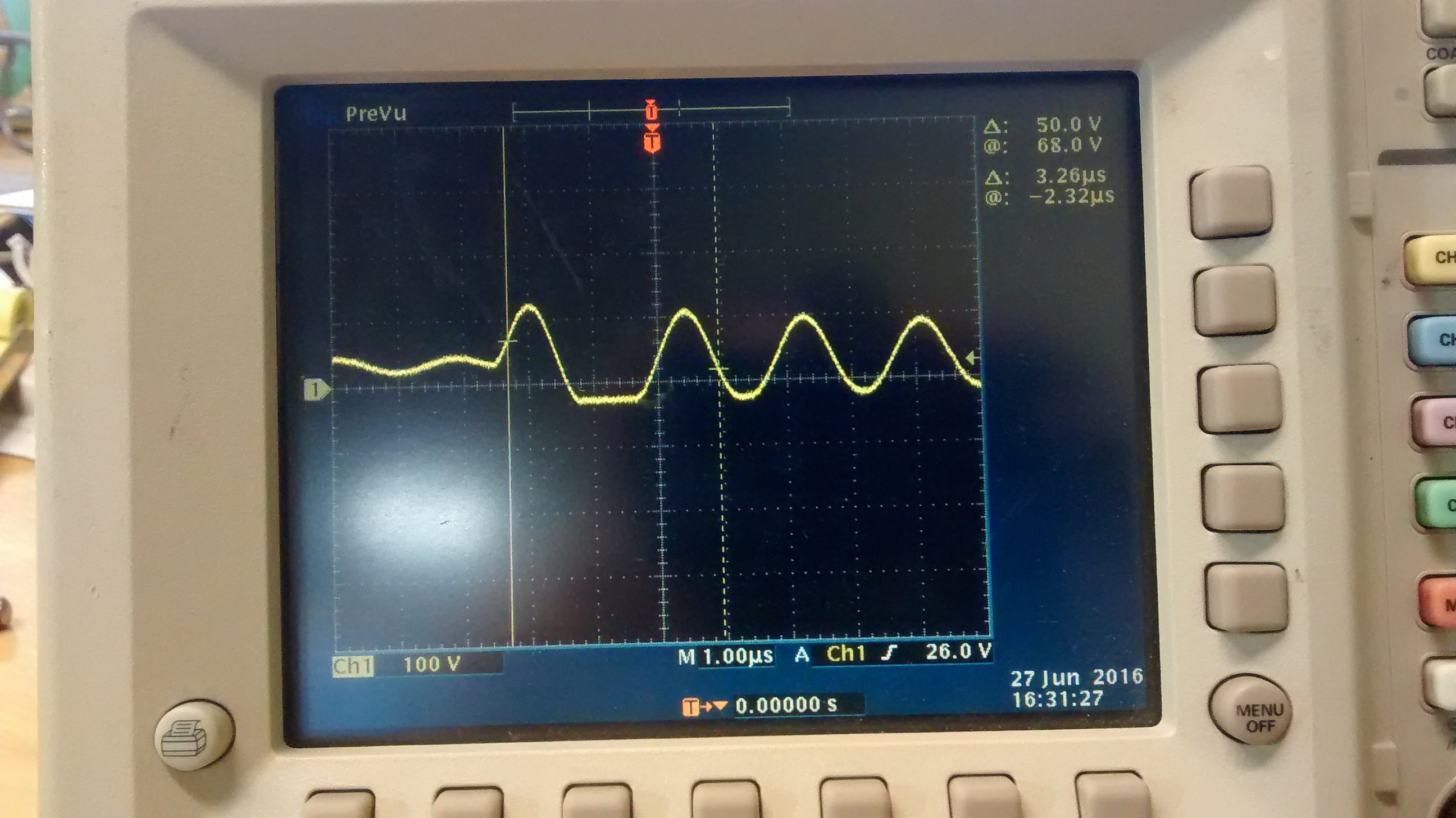
- Please zoom-in\show 2 or 3 pulses of the D4 voltage waveform. Its not clear, so if possible you may need to get the current through the 470mH inductor at startup on the failing boards.
Sure, see attached. File name: D4_zoomed.jpeg
- How did you measure the current going into PIN5? It is better to check using a small current probe connected to the o-scope.
Pin 5 jumper-wire through a current meter to L1 & C11 junction.
7) MOV
- Is the MOV rated 910V ac or dc? Since your max AC input voltage is only up to 277Vac, you may try using an MOV rated for 300V or close to it. Do not use MOV with very high rating. 300Vac MOV will be cheaper and will clamp at a lower voltage.
We wish we could, but UL makes us use a higher rated MOV. Even though our max input voltage is 277 VAC, UL says our Surge Protection Device (in this case, the MOV) has to not blow up if the electricians wire up the 277 wrong. When 277 is wired wrong, you get 480 VAC. Thus, our MOV has to be rated for 480 VAC or higher. L
8) “Fully built boards fail consistently at 4 kV surges. Boards where only the power supply are built up consistently pass at 4 kV.” – We made a slight modification to the partially built boards, which was replacing the 470uH with a 1.0mH inductor of a different construction type. This change was prompted by an unrelated fix, but no fully built boards (by the manufacturer) reflected this new component as we believed it was unrelated – not an intuitive fix as they are similarly rated.
We now see that this component change fixed our problem, but the reason WHY is not perfectly clear. The saturation current for the 1.0mH is 0.3A and the saturation current for the 470uH is 0.21A. These values are very close considering the magnitude of the voltage applied.
The fully built boards feature the 3.3V regulator powered by the LNK chip. We also believed this to be an issue but failures occurred with and without the component placed.
- How much load current does the 3.3V draw from the 5.0V output? - In other words what is the power drawn by the 3.3V output at start-up at normal steady state operation?
Start-up current draw: 23.22mA
Steady-state current draw: 21.38mA
- For the boards where only the power supply were built, was the relay connected? meaning was the 5.0V output supplies the relay at that time triggering the relay? How big is this relay by the way, (current of the relay)? This maybe causing your failure during start-up where this relay will load additional current from the 5.0V output.
We tested some boards with the relay connected and some without. The same failure was observed.
- Try removing the relay, unmount it from the board. Put back the 470uH and power-up the complete fully built board without the relay only.
Failure occurs whether or not the relay is placed.
- Try also, instead of removing the relay, remove the 3.3V regulator from the board to validate which is causing the failure. If the 3.3V regulator is really causing the failure, then this must be drawing a large current from the 5.0V regulator. But, evenso, the LNKSwitch should protect from over power or short circuit conditions.
The board fails with and without the 3.3V regulator being placed.
9) The current sensing circuit (U9), and the relay (K1) were on the HV/LV barrier. We suspected there was a sneak circuit involving these other two components. Failures still occurred with them removed.
- You mean you physically removed the relay from board and still there were failures with the 470uH?
Correct.
| Attachment | Size |
|---|---|
| C11 (DC coupling).jpg (1.13 MB) | 1.13 MB |
| D4_zoomed.jpg (1.06 MB) | 1.06 MB |
HI,
I am a bit confused.
You mentioned that the failure will occur only if the board is fully built with complete circuits and using the 470uH. And that there is no failure only when 1000uH was used with the power supply section mounted only.
Now, you mentioned with or without these 3 [the 3.3V regulator, the relay and the current sense] there will still be failure as long as you are using 470uH? - That means there are no other circuits that are being supplied by the 5V output, which is equivalent to a NO LOAD on the 5V output. Without any circuit connected to it, is the output voltage level shoots up higher than 5V?
Is it possible for you to do these that I asked in my previous reply?
Do this:
1) With the power supply only mounted\built on the board, using the 470uH, remove the 3.3V regulator and the relay. Power up the LNK306. Using an E-load, increase the load current until the LNK306 will enter the power limit. Record the max output current that you were able to load before it goes to power limit. After this, change to 1mH inductor. Repeat the same procedure.
2) Power-up a completely fully built board. The relay, sensing circuit, the 3.3V regulator should be there and use the 1mH inductor. Will it pass? You need to do this to validate the fix. Test in at least 3 boards.
3) Change the LNK306 and use LNK302. You may keep the same input capacitors and use only 1mH. Test in at least 3 boards. If it works reduce the input capacitors to 4.7uF and check again.
4) Send a picture of the complete board if that is ok.
Thanks & Regards,
PI-Picard
I am a bit confused.
You mentioned that the failure will occur only if the board is fully built with complete circuits and using the 470uH. And that there is no failure only when 1000uH was used with the power supply section mounted only.
Elaborating on our testing history:
We had a small supply of boards to test the design, a rare failure mode was the LNK chip failure on start-up. We later found the failure mode could be reproduced by introducing transient surges. It was not intuitive to assume the inductor was an issue because it was adequately rated to survive these transients as per the MOV specs and the data-sheet specs for the LNK306.
We believed the failure mode was a result of some component on the 5V or 3.3V rail providing a sneak circuit for current to destroy the LNK chip. However, our testing has confirmed that failures will occur with or without the 3.3V regulator (thus, no 3.3V components powered) and with or without the 5V supplied relay.
Alongside this, a power supply change was also being tested (which included the 1mH inductor) for an unrelated issue, and because we believed our issue was a sneak circuit, it was not immediately implemented. This change was not yet committed to the manufacturing process, by manually integrating the new design we found the problem to lie in the inductor by process of elimination.
This part is the most confusing. The 470uH inductor which failed had a surface mount design, we found that a through-hole 470uH inductor NEVER failed after many tests (however, we are still switching to the 1mH due to the other issue it solved). Below is the data sheet information provided for each:
SRR7045-471M (Surface Mount):
uH: 470
Tol.: +/- 20%
Q Typ: 80
Test Frequency (MHz): 0.796
SRF Typ. (MHz):3
RDC Max. (ohm): 1.1
I rms MAX (A): 0.32
I sat Typ. (A): 0.22
RLB0914-471KL (Through-Hole):
uH: 470
Tol.: +/- 10%
Q ref: 20
Test freq. (MHz): 0.796
SRF (MHz) min.: 1.8
RDC Max. (ohm): 1.3
IDC Max. (A): 0.50
RLB0914-102KL (Through-Hole):
uH: 1000
Tol.: +/- 10%
Q ref: 40
Test freq. (MHz): 0.252
SRF (MHz) min.: 1.3
RDC Max. (ohm): 2.1
IDC Max. (A): 0.30
Now, you mentioned with or without these 3 [the 3.3V regulator, the relay and the current sense] there will still be failure as long as you are using 470uH? - That means there are no other circuits that are being supplied by the 5V output, which is equivalent to a NO LOAD on the 5V output. Without any circuit connected to it, is the output voltage level shoots up higher than 5V?
Yes, without the 3.3V regulator the voltage increases to 50V if all capacitors are present.
Is it possible for you to do these that I asked in my previous reply?
Do this:
1) With the power supply only mounted\built on the board, using the 470uH, remove the 3.3V regulator and the relay. Power up the LNK306. Using an E-load, increase the load current until the LNK306 will enter the power limit. Record the max output current that you were able to load before it goes to power limit. After this, change to 1mH inductor. Repeat the same procedure.
470uH Max Current: 33mA
1mH Max Current: 46mA
2) Power-up a completely fully built board. The relay, sensing circuit, the 3.3V regulator should be there and use the 1mH inductor. Will it pass? You need to do this to validate the fix. Test in at least 3 boards.
We have already done this, they pass.
3) Change the LNK306 and use LNK302. You may keep the same input capacitors and use only 1mH. Test in at least 3 boards. If it works reduce the input capacitors to 4.7uF and check again.
We don’t have an LNK302 available to use. We chose the LNK306 for its greater current output.
4) Send a picture of the complete board if that is ok.
Attached.
| Attachment | Size |
|---|---|
| side-by-side.jpg (605.24 KB) | 605.24 KB |
Hi,
Thanks once again for those information.
Its really hard to understand without the properly measured waveforms during failure.
Since this is a buck converter the Vds should not go higher than the input voltage.
If there are no other circuits connected to the power supply the output voltage will shoot up, therefore, you need to put a pre-load. Tweak the resistor value such that the 5V output is still within acceptable regulation limits when there is no other circuit that is connected. Strike a balance between the target efficiency and the output voltage regulation.
So far, based from what we had discussed the failure is only happening with a SMD 470uH inductor. This repeatable failure was that verified by injecting transient surges or just through the normal power-up? What if you do a normal power-up\start-up using the SMD 470uH inductor, will it always fail?
Can you measure the actual resistance and inductance of the SMD 470uH, through-hole 470uH and the 1mH through-hole inductor? It will be better if you can use LCR meter to measure those.
Regards,
PI-Picard
Any thoughts or comments on this would be appreciated.
Brent