

LNK305 - Took oscilloscope readings, lots of noise on power rails
Hello, I am using the LNK305 to create a 5 volt power rail, and a LDO (MCP1700) to create the 3.3V power rail. I have an RF module onboard that is sensitive to noise on the power supply. I took some oscilliscope readings to see just how much noise is present, and this seems like a lot?
Is this typical and is there a good way of reducing this noise?
(see attached photos)
评论
Hi,
Can you please share the schematic and transformer design files?
PI-AP
Hi,
Can you please tell how and where are you probing to capture the attached waveforms?
What is the load condition?
The frequency/ period which is shown in the scope window, what is the frequency for?
PI-AP
Hello, I attached the schematic and layout for the power.
I plugged the lnk305 device into a 120 volt isolation battery, and used a "RIGOL DS2202A" oscilliscope, putting the ground probe on the 12ov neutral line (next to C8), and then probed the 5v rail (next to C8). I then probed the 3.3v rail directly after C11.
I am assuming the frequency is showing the frequency of the peaks?
I shared the schematic a while back, just checking back in?
I shared the schematic a while back, just checking back in?
Just checking back in. Not sure whats going on here? Any help or advice would be greatly appreciated, thanks.
Have you tried using a post filter? What is the frequency you have designed for operation? I see different values of frequencies in the screenshots, Why isn't it consistent? What is changing the frequency value? Also the output voltage ripple seems to be huge, why is that so?
We need these information to understand what is going on.


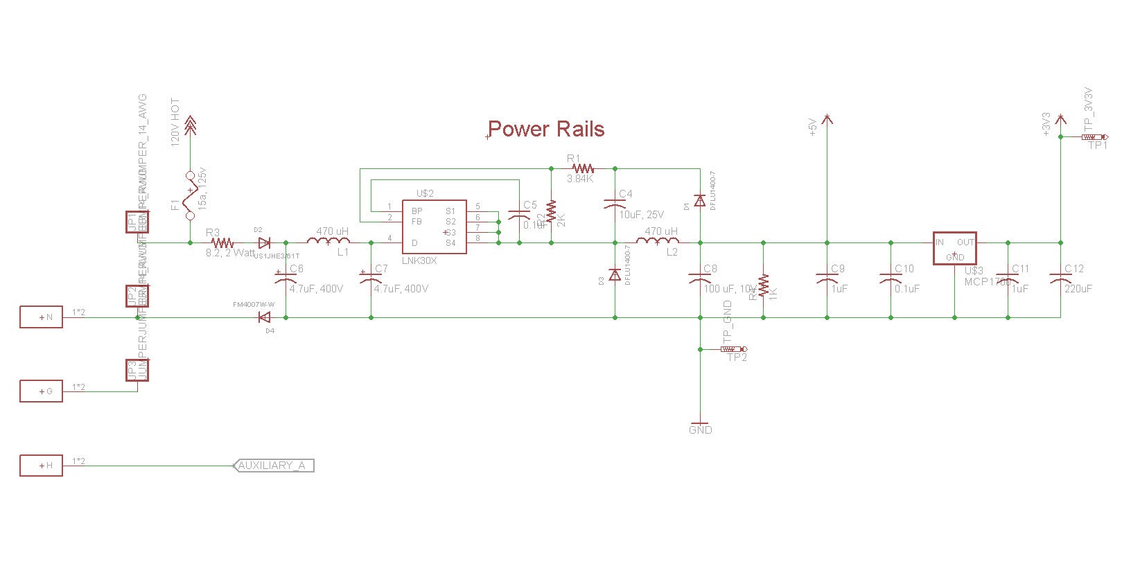

Hey guys, I could really use some advice on this subject.
I tried swapping out the output capacitor (100 uF electrolytic low ESR) with a ceramic 100 uF capacitor, and it didn't seem to change a thing.
Is there anything else I can do to stabilize this a bit more? Would a specific ferrite bead in serial work? An low pass RC filter circuit? I don't really know what to do.