

LNK302 - Input protection
Hello,
I use LNK302DN to supply a small module installed under the light switch. I attached the schematic for the power supply. In lab everthing works well, however I have some problems with self erasing EEPROM memory for microcontroller (Attiny84). For 50 devices installed on field it happend that after power down in mains, the eeprom memory has been erased. Could you help me what the problem could be? Could there be spikes before the power shutdown that could erase the MCU eeprom.
Also I woul like to ask could you recommend some circuit protection. I thouht about a varistor on input and a TVS diode on the 5V line.
コメント
Thank you for the information. I noticed that I used RG1JL diode, which has maximum recovery time 250ns. The design worked fine, however could that introduce some problems?
Hello electrobody,
Freewheeling diode should be an ultrafast type. For MDCM, reverse recovery time tRR ≤75 ns should be used at a temperature of 70 °C or below. Slower diodes are not acceptable, as continuous mode operation will always occur during startup, causing high leading edge current spikes, terminating the switching cycle prematurely, and preventing the output from reaching regulation. If the ambient temperature is above 70 °C then a diode with tRR ≤35 ns should be used.
For CCM an ultrafast diode with reverse recovery time tRR ≤35 ns should be used. A slower diode may cause excessive leading edge current spikes, terminating the switching cycle prematurely and preventing full power delivery.
Fast and slow diodes should never be used as the large reverse recovery currents can cause excessive power dissipation in the diode and/or exceed the maximum drain current specification of LinkSwitch-TN.
In you case, depend on how much current the output need. if it is lower than 63mA, it should be MDCM design
Best Regards
Great, thanks! I will replace the diode to faster one. The circuit takes 15mA (MCU and Radio) and 35mA or 55mA maximum (from 12V) with one or two Relays on.
We use AVR in our design, I found information that designers encountered problems with EEPROM while using it. It's probably because of spikes in the supply. Could you recomend us some solution that would help to reduce the spikes? It might not be connected with power-down, eeprom could be damaged earlier and power down just showed up the problem (the data was kept in RAM). The device is working with roller shutter motor which generates a lot of noise.
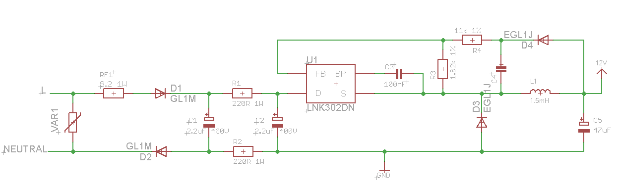
I updated the power supply schematic. Could youkindly have a look on it? I have some doubts. We hava little PCB board space, so some elements are changed.
RF - it's 1 W fusible resistor
R1 and R2 are 220R 1W SMD 2512 resistor or melf 0207
D1 and D2 GL1M diodes
C1 and C2 2.2uF 400V Rubyconn Capacitors or 3.3uF 400V caps
C3 is 100nF 1206 ceramic capacitor 50V
D3 and D4 are EGL1J fast diodes Vrrm 600V, trr<75ns, Vf < 1.8V
C4 is 1uF 100V 1206 ceramic capacitor
C5 is Panasonic LOW ESR 47uF capacitor
Coil is Ferrocore DLA1500 DCR=25, Idc=100mA
Questions:
- Is it necessary/recommended to have R2 and D2 on the N line?
- Is it ok to have both diodes the same fast type EGL1J?
- Is it ok to replace the C4 1uF with ceramic cap?
- Will coil with Vdc=100mA will be enough on this design? It's very small 4x11mm, so it's handy.
How should we validate/test the circuit before launching to market?
| Attachment | サイズ |
|---|---|
| power supply.png (15.84 KB) | 15.84 KB |
Hello electrobody,
here is the answer:
- Is it necessary/recommended to have R2 and D2 on the N line?
the R2 and D2 is used here for surge concern. Depend on your surge requirement, it may be able to be removed. But you need to verify your surge test and EMI test to make sure the performance is acceptable
- Is it ok to have both diodes the same fast type EGL1J?
It is OK. D4 can be a low-cost slow diode such as the 1N400X series, however it should be specified as a glass passivated type to guarantee a specified reverse recovery time.
- Is it ok to replace the C4 1uF with ceramic cap?
Capacitor C4 can be a low cost general purpose capacitor. It provides a “sample and hold” function, charging to the output voltage during the off time of LinkSwitch-TN. Its value should be 10 µF to 22 µF; smaller values cause poorer regulation at light load conditions. if you want to use ceramic cap, it should be X7R or better and 10uF or bigger. if you can verify the DC bias and thermal variation of the capacitor. it should be OK to use.
- Will coil with Vdc=100mA will be enough on this design? It's very small 4x11mm, so it's handy.
It is a little bit small. the saturation current of the inductor should be higher than 146mA. Rated current or RMS current should be higher than 70mA.
Best Regards


Hello electrobody,
After the main power down, the circuit will stop working and supply the 12V. If the EEPROM is erasing, it should be microcontroller problem. you should contact them.
For the spikes at the 12V output side, it will not have spike during power shutdown. However i suggest you to connect some pre-load at the 12V output side, like 4kohms or 2.4kohms. In this way, you will not have any spike even when the microcontroller is not working.
As for the protection consideration, it depends on what kind of protection you need. If you want to do some protection for surge at input side, you can have some MOV on the AC input side.
Best Regards