
DER 136 Design Having problem in my PCB
Dear Friends
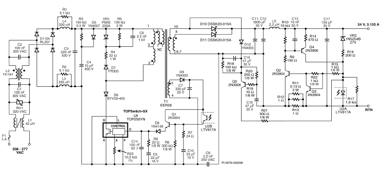
i have been using the DER136, and i have copied the schematics from DER136.
I have developed the Boards.
1. If i removed all the transistor then i am Having a 27 voltage of Output which is expected in cv Mode.
2.Now, if i soldered the Transistor 2N3906 and 2N3904, At output nodes, i am getting the 13Volt outpur at no load and at load conditions it drops down.
Some observations are here,
a) Base(Q2)=1.09v
b) Base(Q3)=0.6v
c) Base(Q4)=0.9v
This 3 transistors are used for the CC Operations.
Kindly help me what to do. or How to troubleshoot.
Link for the DER 136 is at down
https://ac-dc.power.com/design-support/reference-designs/design-examples/der-136/
Comments
Hi Magicianchiku,
Thank you for using our DER136 as your chosen charger design.
I have below clarifications:
1) Did you copied evrything there in the schematic including the values and parts stated without any modifications?
2) If you followed and copied the same schematic as DER136, have you checked the output feedback control circuit for wrong values or faulty parts?
2) What load condition was it when the output voltage drops down? What was the voltage level it dropped to?
3) Why did you have to remove the transistors to get the CV mode?
Regards,
PI-Picard
PI-Picard:
Hi
it was problem in the Transformer. so i have made again new pcb and new transformer and tested now it is working.
The cv Functions Properly.
in the same circuit: if i remove R9, Then it works for the cv perfectly and i can load the same at 1.5 amp.
if i insert the R9 then it drops to 12.5v without any load connected to it.
I have tried all the troubleshhot ways but unfortunately PNP Transistoe turns on which drive the Opto and giving output of 12.5v.
i Dunno what sections need to be checked.
pls help me out.
| Attachment | Size |
|---|---|
| der 136.PNG (78.34 KB) | 78.34 KB |
Hi,
With the help of Field application Engineer,
i removed the R21 Resistor, Now the output is Oscillating->Image attached
it clearly indcates that,It is not dropping below 24volts so CV is functioning.
The waveform captured at no load conditions.
Kindly guide to Troubleshoot the same.
| Attachment | Size |
|---|---|
| IMG_20160801_180000.jpg (1.63 MB) | 1.63 MB |
Hi Magicianchiku,
When you say remove R9 or R21 did you mean removing it without replacing the location with a physical short? Which means you left it open? What is your constant current requirement (CC)?
Also, kindly clarify if you copied everything in the schematic of DER-136 that includes all the values. Are your requirements the same as the DER-136?
I attached the DER-136 document, please read section 5.4 and 5.5 so you can understand the operation. From there, you will find ways to troubleshoot the problem. I would recommend the same.
Let me know if you need further help.
Regards,
PI-Picard
| Attachment | Size |
|---|---|
| der136.pdf (2.03 MB) | 2.03 MB |
Hi Magicianchiku,
Looking for the correct values depends on your CV\CC profile requirements. You will need to tweak the values to get your desired response. Since the CC was triggered when you put back R9, then you need to adjust the resistors driving the transistors. For starters, play around R9, R22, (R11, R12, R13), R14 and R15. R21 is for soft start\startup. What happens to the output voltage after a while? Will it stop oscillating?
Regards,
PI-Picard
Having problem at the startup at ac inlet.
With the Variac it gets on.
but during direct ac through the ac inlet with the full load at the Ouput the TOP IC IS BLOWING
Hi Magicianchiku,
Can you send me your latest schematic where this problem occured?
Please send also the PIXls and PIExpert that you used.
You mentioned using the Variac the output turns on and the board is working perfectly? Does this mean at full load? What was your AC inlet input?
At 50% load, was it working during direct AC inlet? Using the AC inlet, can you send the VDS drain voltage and current waveforms at the maximum load where it is still working fine?
Have you consulted the application engineer on this?
Regards,
PI-PICard
I am expecting a charger to charge the Battery.
wth the CC/CV Operating Modes.