
SMPS output voltage drops
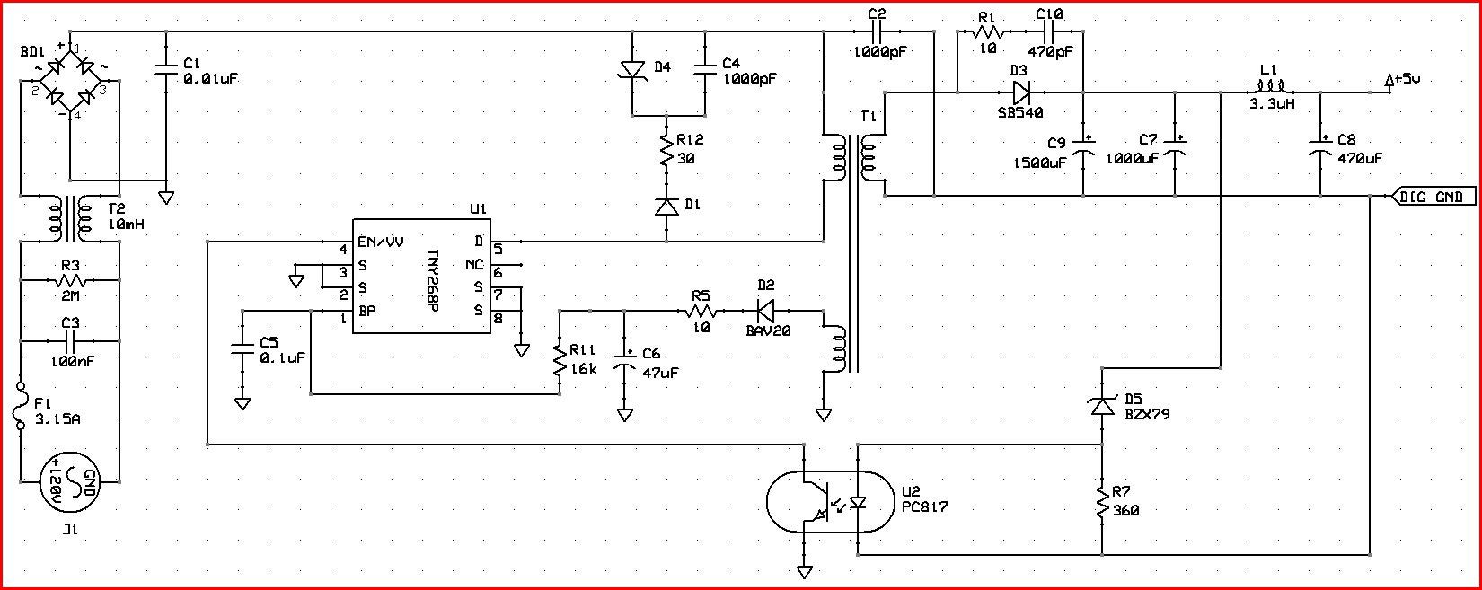
I'm working on a project where I'm required to design a SMPS to drive a CREE RGBW LED. I'm using the design example report DER-11 to do so. This article application is for PC standby purposes. I'm looking at the output characteristics (5V/3A)and I think is enough for my application (5V/1.8A max). I constructed the above mentioned SMPS to power my circuit which consist of 1 microprocessor(for communication purposes), couple resistors and and 4 A6281 current drivers. When I'm testing the system and measuring my SMPS output voltage, this voltage decreases as my current increases when the LED intensity increases. I don't have a lot experience with this type of power supplies so I can't figure out what is causing this problem. It is important for me to have a constant voltage (5V) supply since the microprocessor and current drivers are required to be powered with 5V. One stage that might be causing this problem is the feedback loop using the PC817 optocoupler, but how can I test this? Therefore if you can provide me some suggestions about this design I'll really appreciated.
Comments
Thanks for your reply!
These are the answers to your questions:
Did you make your own PCB layout
Yes.
Did you follow the PCB layout guidelines in the Appnote?
Yes
Where did you get your transformer
CWS coils. TN268-P01MS. According to the manufacturer this transformer is meant to work with the TNY268
Do you have an approximate curve of load current vs. voltage you can show?
No, but I can make one.
4) What type of capacitor is C9? Is it a low ESR type?
I bought it from digi key. The data sheet doesn't mention anything about the ESR value. Below is the link from the manufacturer is case you can derive the ESR value from the info provided.
http://industrial.panasonic.com/www-cgi/jvcr13pz.cgi?E+PZ+3+ABA0108+EEUFM1A152L+7+WW
Now I'm searching on how to measure ESR levels to see if I can derive some value and then publish it here.
I will follow your last suggestion and see how it works.
Thank you
Javier Real
According to this, FM series is "low impedance" which means low ESR:
http://industrial.panasonic.com/www-data/pdf/ABA0000/ABA0000PE285.pdf
So this is not likely the cause of your problem.
Can you post an image of your PCB layout?
Pls. also post the load current vs voltage. Do it for 180 VAC input and also at 265 VAC.
Lastly, do you have the transformer specs, and how does it compare to the original design? (primary and secondary turns, core center leg area, primary inductance, and leakage inductance)
Dear PI-Tucker:
Thanks for the info about the capacitor.
I'm working on the I vs V plot, I will post it ASAP.
For the transformer specs, I request a data sheet from the manufacturer since they do not provide any info in their website.
PCB layout I have to find the way to post it since I'm working with a two layer design and is kind of messy if I just post it as it is.
An additional question: I was reviewing many different design applications from PI and I noticed that the input capacitor is always "bulky". Now in my design since I am required to make it as small as possible, I was able to find the same rated capacitor but in a SMD package. Is this capacitor selection affecting my output regulation?
Additionally I was reading some documentation from PI University, and one of the reasons for not reaching regulation is a wrong primary side transformer polarity. It is safe to just swap this input pins and test it? I'm asking this because at the beginning I was working on a different design, with a different manufacturer chip, and when I did this the chip blows out really bad!!!
Thank again for all your feedback information.
Javier Real
PI-Tucker
Attached are the waveforms for the drain voltage, input capacitor voltage and BP pin voltage. Hope these waveforms helps to understand a little what is going on in this circuit.
Additionally these are the measurements that I was able to take:
1% load : 4.99V
25% load: 4.95V
50% load: 4.89V
75% load: 4.82V
100% load: 4.67V
Input voltage is 120VAC
Thanks
Javier
I just realized you have a .01uF capacitor for the input capacitance (C1).
Are you trying to achieve high power factor?
If so, you should look at the LED design examples we have that are designed for high power factor.
We have a page which specifically discusses LED drivers. Some of the example designs we have have high PF.:
http://www.powerint.com/en/applications/led-lighting
Here is one such example, which uses the "valley fill" circuit for high PF:
http://www.powerint.com/sites/default/files/PDFFiles/di130.pdf
You need to follow one of those circuits.
No I'm not trying to achieve high power factor.
I just need to have constant 5V and up to 1.6A at the output. Current levels are fine but the circuit is not regulating 5V correctly. I just replace C1 for a 100uF 400V bulk capacitor but still having regulation problems.
Thanks
Javier
Pls. show Drain voltage waveforms again at full load.
Also, the circuit has a constant voltage output.
LED's need a constant current source power supply. Does your LED string have a current regulator?
Yes each LED has a current regulator. That's why I need 5VDC in order to power these chips.
Please, attached are two waveforms
Voltage Drain 1 : Using 220uF 400V C1 capacitor
Voltage Drain 2 : Using 0.01uF 1kV C1 capacitor
Thanks
Javier
Are R12 and D4 getting hot?
neither R12 nor D4 are getting hot their temperature is 78F. But R11 is at 120F; R5 at 109F; D2 at 110F and U2 at 112F.
hello sir i am working on the Reference Design Report for a 6 W Constant
Voltage (CV) Adapter Using LNK625PG . sir i am not getting the required output voltage of 5V .
sir i had attached the reference design also with this text.
| Attachment | Size |
|---|---|
| rdr201.pdf (1.12 MB) | 1.12 MB |
Hello,
Thank you for considering Power Integrations for your power supply application.
Can you please share your schematic and PCB documentation that you are using? Are you using the https://ac-dc.power.com/sites/default/files/docs/rd201Gerber.zip as your reference?
Can you kindly also share your Transformer documentation such as the one got from the PI Expert Tool on pour website?
Best Regards,
PI-Kryten
1) Did you make your own PCB layout)
a) Did you follow the PCB layout guidelines in the Appnote?
2) Where did you get your transformer?
3) Do you have an approximate curve of load current vs. voltage you can show?
4) What type of capacitor is C9? Is it a low ESR type?
a) If not, the opto may have been damaged - try replacing your opto and adding a 10 ohm resistor in series with the opto LED, and also replace C9 with a low ESR type.