
Failure of LNK419 and blow the LED
Hello,
Detail of driver :
- Topology: DER-344 example : 12.8W Tapped Buck Led Driver
- Input: 185-265 VAC
- Output: 20W – 20Volt 1Amp
- Usage: Outdoor Streetlight
- Testing: 24Hour with high temp, Lower & higher volatage applied, 1 lac time on/off tested
- Protection: No open voltage protection applied as it not needed
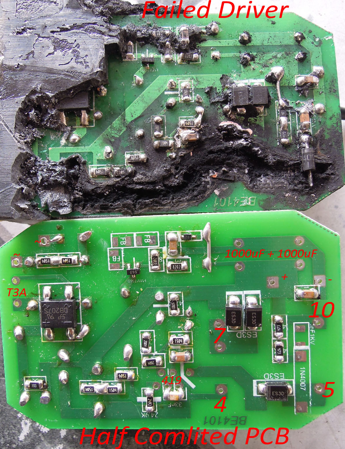
Driver condition after failure:
- L2-S of LNK419 - D of LNK419 - D3 - pin#5 of T1 track was fully burn.
- D2 Diode also burnt up with track
- Led was also burnt
- LNK419 IC burnt
- Failure Ratio: 5 failed out of 15 drivers after 2 month of usage
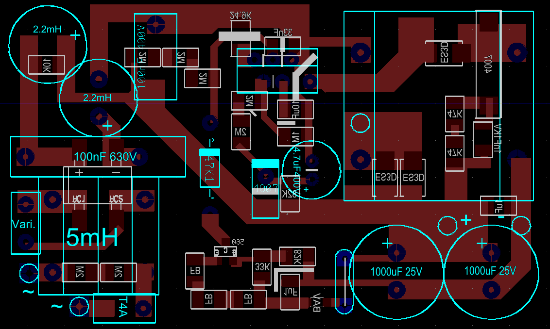
Changes made on DER-344 (Circuit diagram file attached) – To meet my reauirements
- Added 8mH filter chowk as emi filter after fuse.
- R3 + R11 : 4M to change maximum voltage shutdown
- R5 : 1.5M to change minimum voltage shutdown
- C8 : 33nF 100V for better regulation
- D2 : ES6D (ES3D x 2 parallel)
- C5 output cap: 2000uF 25V (2 x 1000uF 25V) for better THD
- C3 : 4.7uF 400V for better surge protection
- U1 IC : LNK419 to make 20W driver
- C4 bias Cap: 10uF to run on reduced power mode
- VR1, VR3 : removed not needed open circuit protection
- Driver was potted with PU epoxy.
I have made 20W and 30W non dimming driver with potting and it running since 1 year. I have never seen problem like that before.
Please let me know the reason of IC failure. Because I have sold many items with this driver recently.
Files
| Attachment | Size |
|---|---|
| PCB Layout | 95.08 KB |
| Failed Driver with real PCB | 517.52 KB |
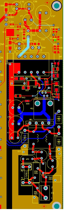
| Circuit Diagram with changes | 79.88 KB |
Comments
thanks for your answer.
I will sure contact the local PI regarding this issue.
But can you still watch at my circuit diagram. Please have look at the diodes, inductor and other components and let me know circuit diagram is okay or not.
It's only fault of PCB layout ?? Because I have made many PCBs using linkswith-Ph and never found problem like this. All of PCB layout are similar.
Look at circuit diagram if you got time for it.
Thanks in advance
Hi
I don't see any obvious problem on your schematic.
1. I'm just curious why D2 burned. If possible, can you probe the current at D2 at high temp (just heat it up with a heat gun or something else) and see if reverse recovery increases abnormally. I was suspecting that probably it starts with this diode since the original schematic is using a a schottky diode.
2. On the layout, C4 directly connected to the source is OK (ideal connection). However, one possible problem is the ground connection of C3. The charging current of C3 (peak detect capacitor) can inject noise on BP on your current layout and can be possible source of problem.
C3 gnd or return SHOULD NOT connect to C4 going to the source. If possible, cut the trace connecting C4 and C3 gnd or return and connect C3 gnd directly to the source or negative side of C2. This will eliminate noise injected on the BP pin.
Regards
I have written D2 by mistake actually D3 has burnt up.
Anyways I will try to resolve pcb layout issue and try it again.
But is there any proper way to check surge protection ?
Currently I can test following ways.
- On/off test with timer
- Voltage high, Voltage Low using variac
- Heat test with putting driver inside box
Let me know if any other easy way to test pcb for surge protection or other protection.
Line surge and sag is usually tested with a programmable ac source. If you don't have a programmable ac source, what you're doing now I guess is sufficient.
For surge testing, which simulates high frequency voltage surge due to lightning strikes, you definitely need a surge generator to apply the standard waveform. The standard ac on and off cannot duplicate the waveform required by this test.
Hi,
For cases like this, you need to contact a local PI fae in your area to be able to have the board tested and look for the possible cause of the problem. He will then guide you on the possible steps necessary to resolve the problem.
Regards